I’m just putting this out here in case others have had to deal with this problem and can offer any tips.
I have 16 Walthers #4 DCC friendly turnouts and 4 curved turnouts for my modest layout. I have installed half of them which are wired and soldered to tracks. I should mention that these were all purchased about three years ago when I first started planning my layout so they are not recently manufactured.
And, this is my first and only build. (It’s an age thing). Amateur me.
I discovered that about 2/3 of them have continuity failures between the short wiring strap that connects to the frog and the frog itself. Some research tells me that others have had to deal with this problem. I’m going to abandon all the wiring tabs and wire directly to the frogs for the polarity control from the switch motors but it appears to be a very delicate operation as the frogs don’t leave much room for soldered wire connections; they are heavily insulated.
If anyone has dealt with this issue before I’d appreciate any advice.
I just repaired a #6 last night. One of the 3 insulated rails was dead.
I tested a few others that were nearby. One turnout on a double crossover has the same issue. I thought maybe I have been too rough with them or something. I really don’t like the way these are done. I’d rather see soldered jumpers i instead of the contact approach.
I am only getting around to powering all my turnouts as install servo switch machines
I’m having a little trouble understanding your problems, maybe this is similar.
I used Kato Unitrack on a small semi outdoor layout I have for a couple of years in a temporary location. In a couple of my switches, the closure Rails, as you call them on your diagram, went dead due to outside air oxidizing in the contacts someplace.
Here is the “Southern engineering” solution to that problem. I hate soldering anything. Almost as much as I hate building.benchwork.No soldering needed here! A track nail was wedged up between them to look like some kind of bracebar. No soldering needed here! Perfect operation!
You would hope so but apparently not.
Researching tells me that the wiring strap to the Walthers DCC friendly frog is soldered or “pressed” in the molding process. On close examination I can see that the wiring strap is actually molded into the tie that it is aligned with, so where the connection is made is not really evident.
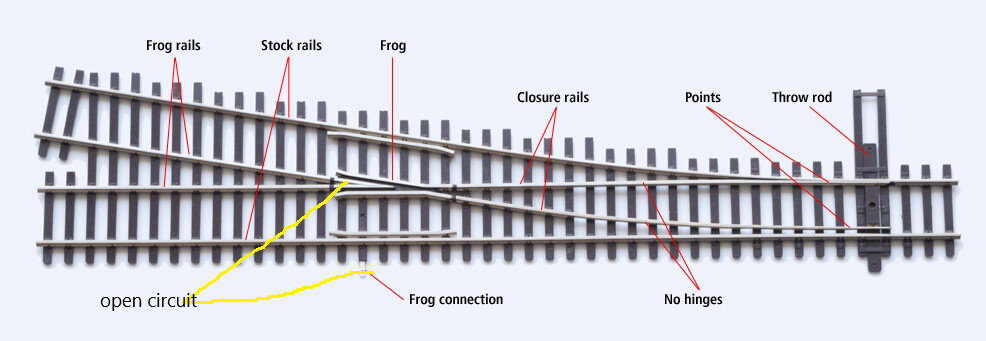
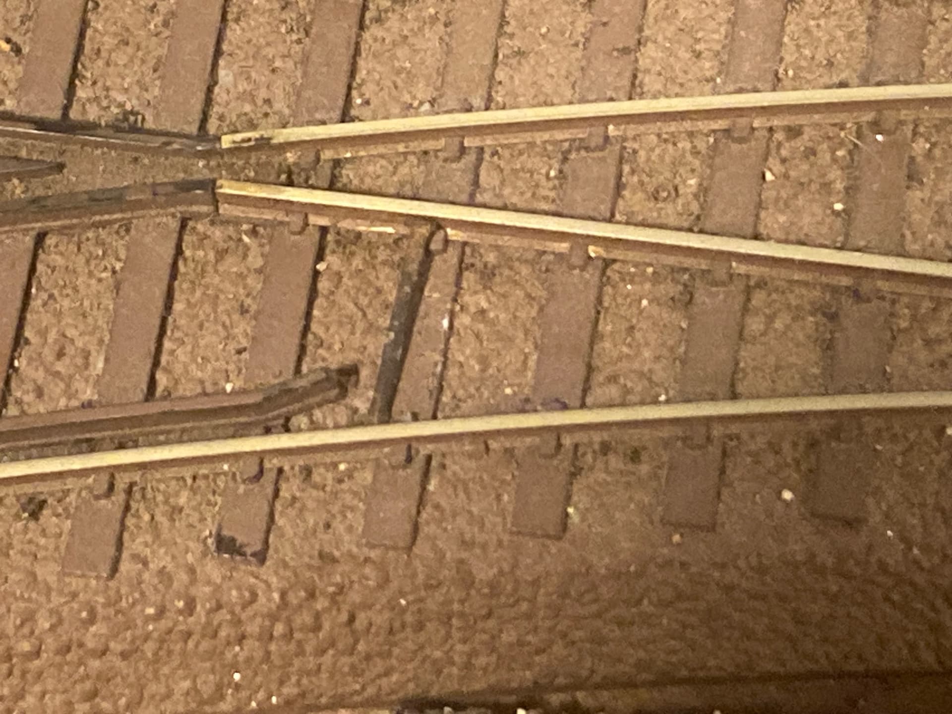
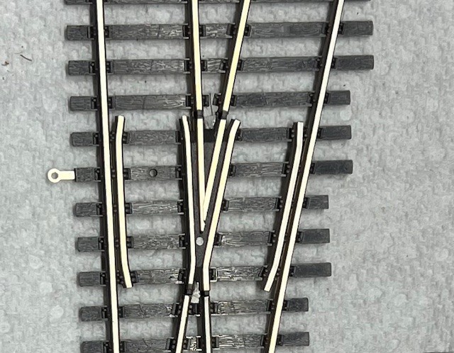
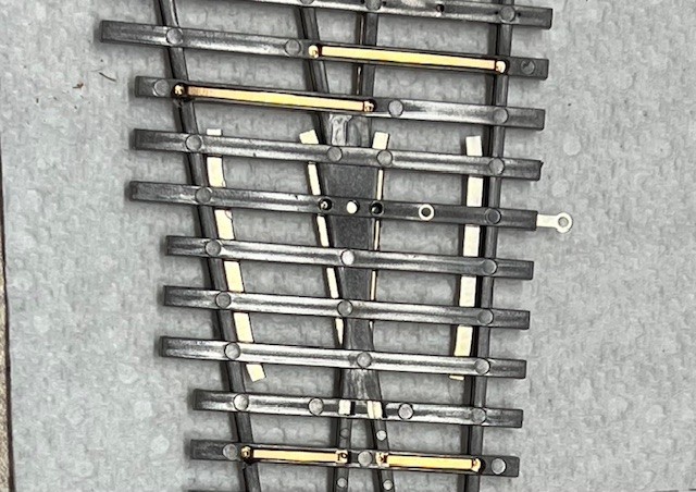
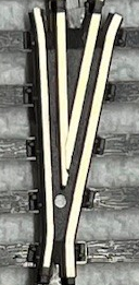
Here are a couple of photos of one of my Walthers #4 turnouts showing both views of the frog and frog wiring strap areas. A bit of lighting glare.
Those straps are quite similar to the old Walthers Shinohara straps. If they were soldered, it wasn’t at all obvious, at least not to me. They seemed pressed into place. I was constantly losing connectivity on double crossovers. I wound up soldering thin gauge wires across the rails.
richhotrain, IIRC, I used thin insulated wires to make the connections I wanted to “secure”. Once the turnouts were installed I included those wires and theis associated solder blobs, in the process when I painted the rail web.
The straps you see are not the problem.
They all have good connectivity to the rails when I checked.
It’s the frog wiring tab that you can see poking out at the end of a tie and its failure to connect to the frog that is the fault.
It seems to me that the ‘metal’ parts of the frog are retained by split square tabs, locked into holes in the tie. You might have continuity problems if the frog lifted slightly and came away from the contact point of the frog-connecting strip. I would not expect any of the strap connections to be soldered with plastic ties; it looks as if the frog connecting strip is press-riveted (at about the center of its span) by a hollow rivet.
I think that you are right.
After more examination of the turnout, I started to think that the online comment I had seen which was that the frog-to-metal tab connection, that was somehow press fitted, was likely the manufacturing process that was used.
I may not be facing as much work as I first thought. After more continuity readings it appears that sometimes the wiring tab (strip) is connecting only to the center ‘v’ part of the frog assembly. Yet on other turnouts only one or both of the two frog side or guard (?) rails are connected while the ‘v’ part of the frog is not.
So this might give me some options for wiring.
It’s more than a bit exasperating. And, yes, I’ve tested all the turnout frog connections several times to ensure that I’m not fooling myself.
Exposing the metal from underneath is a questionable choice, largely because of the fact that the wiring strap to the frog is actually molded into the plastic track tie. And, of course, it’s not possible on the installed turnouts.
So far I’m looking at wiring to the frog assembly from the rail side and even that depends on the type of fault on each turnout.
I have one spare turnout and I’m considering cutting away the plastic under the frog assembly to see what I’m up against. But with the embedded wiring strap and the heavily insulated frog, this might be a ‘fool’s errand’.
Just to hear what Walthers might say about this issue I called their tech customer service where I spoke with a lovely young lady who could not understand anything I described to her. In her very upbeat fashion she kept insisting that I answer her questions which included power readings, rail strapping, switch machines, etc, etc. It sounded very much that she was reading from a trouble shooting flow chart and in desperation I finally just terminated the call.
Wouldn’t you know it, she called me back to continue and I suggested that I email her the information. I haven’t heard back yet but I am curious about the response.
After that I considered going out to buy a big bottle of Jack Daniels.
LOL
If I understand this correctly, you are saying that you have no continuity between that loop sticking out the right side of the photo and the frog. Is that correct?
Moving to the left, I see what appear to be two holes in that same tie, plus what appears to be a shiny stud between them.
Are any of these locations metallic, and if so do you have continuity between those locations and the loop at the right?
If you have a rotary tool like a Dremel, carefully cutting away the plastic from the underside of the ties should be relatively easy. The removal will not ‘show’ and you can easily backfill with epoxy or putty if wanted. It seems sensible to me to cut a straight groove along the bottom of the tie with the ‘strip’ for a replacement wire, if that turns out to be a concern, and then cut up under the parts of the frog you want to ‘juice’ until you expose enough area for contact. This might be an application for the ‘wire glue’ we were discussing a few months ago…
I assume you have a multimeter that can be used for continuity.
Is there continuity from the frog ‘tab’ to that shiny circle that I am presuming is what holds the strip in the tie?
If you set the turnout on a flat, strong surface and tap the frog sections downward, can you get contact (even if transient or intermittent)?
If you cut away the area of plastic under the area where the ‘strip’ would reach the contact area of the frog:
is there full conductivity from the tab to the exposed part of the strip?
does gently peening the exposed area result in conductivity?
you might drill a small hole in the inner end of the strip suitable for installing a piece of solid wire end, or a chip of solder in flux that could be spot-heated to flow.
This HAS to be a fairly simple common-mode failure to diagnose.
presumably you emailed back that on some turnouts your meter indicates continuity between the tab and wing rails but not the frog.
when this kinda thing has happened to me, i’ve suppressed reporting as an engineer, and just “exactly” answer their questions and give them time to think about it.
I planned on doing the kind of things that you suggest but I need some time to implement them.
This is a busy time of year for me and I can’t devote a lot of time to work on it.
“a fairy simple common-mode failure to diagnose”…??
Well, I have identified the problem but coming up with a fix, especially on the turnouts that are installed is a bit of a challenge. I am still a novice at this stuff, although I think I’m creative enough to work out a solution. Eventually.
Yes, I do use a digital multimeter and yes I have a Dremel which I will use to perform ‘exploratory surgery’ on the frog, poor creature. This will help me to decide, I hope, on how best to deal with the installed turnouts.
Thanks for the comments and suggestions.
I’ll report back as soon as I can.
Yes I did mention that in my email as well as pictures that explicitly illustrated the problem.
You know, I have a lot of patience and tolerance for someone who doesn’t understand (like me) but her questions showed me that she had no understanding at all of how the turnout is supposed to operate and that’s why I decided to email the specifics so that she could discuss it with her peers.
I haven’t heard back yet but there’s no rush.
it almost looks (?) like the entire frog is one piece. the black stuff between the rails looks separate from the plastic of the ties. curious what the circular metal(?) at the point is. Is it connected to either the frog or wing rails
as for a fix, the club actually drills a hole into a rail and solders the feeder into it. you could possibly drill a hole into the frog rails from the inside and attach a feeder.
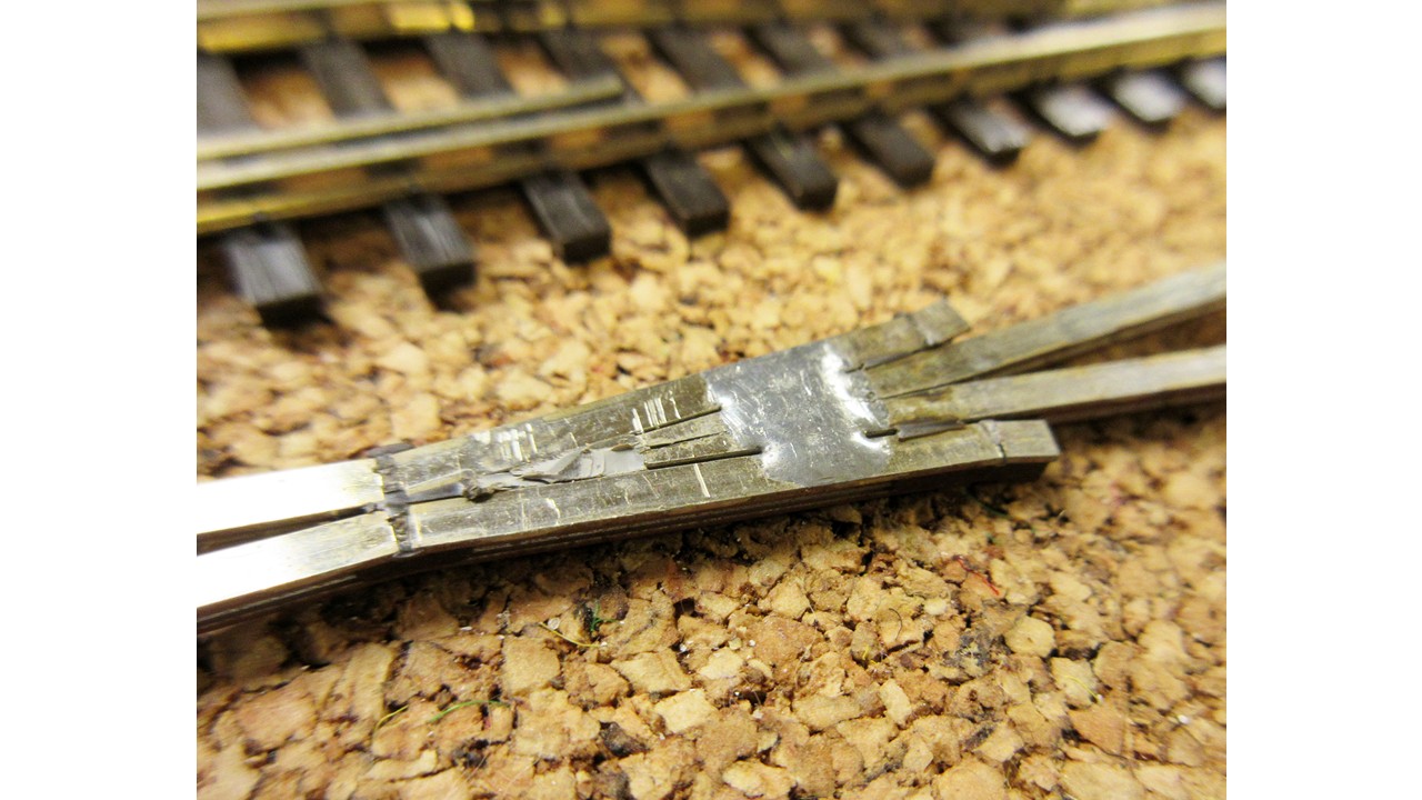
In a 2018 thread, Ed (gpullman) provided a photo of the underside of a Walthers Shinohara turnout with the plastic stripped off. It shows a blob of solder connecting the wing rail to the frog.