I’m trying to understand how welded wheelsets negotiate curves without draging and screeching. From what I’ve read, the concensus is that the wheel treads are tapered and centrifugal force on the car pushes the wheelset toward the outside rail which would make the outer wheel larger in relation to the wheel riding the inside rail. This makes sense up to a point. In a curve the lead engine would ride against the outer rail, with the flange and taper turning the truck into the curve, but the cars in the center of a heavy freight, for example, will be pulled toward the inside rail by the locomotive power up front and the weight of the cars behind. Centrifugal force would not be a factor on a 35 Mph train unless it was being pushed. Perhaps there IS some sliding and draging going on! Any input?
The wheel should not ride against the flange. As the outer wheel rides up only slightly, its diameter gets larger and it will traverse the slightly longer path in the outer rail of the curve. Of course this assumes the wheel is tapered properly and the rail head is crowned perfectly. Neither of these is always true. The rail and wheel shapes are chosen to keep the lateral forces below about 50% of the weight forces downward on the wheel. The real problem is that if the lateral force gets too high, the flange will climb over the rail, derailing the wheel. See: http://en.wikipedia.org/wiki/Nadal_formula
Never heard of a welded wheelset. Wheels are cast steel. They are pressed on to the axle.
You have the right idea about the taper. It causes the wheel set to center it self. In extreme cases the flange comes into contact with the rail but this is only in sharper curves and instances of mechanical defect.
The fact is, they do screech and slide, a just not a lot.
In a theoretically perfect world, with perfectly level tracks, perfectly elevated outside rails in curves, and wheel sets with zero wear on the taper, the above statements about the taper guiding the wheel would work, but I doubt you will find more than 100 feet of “perfect” rail anywhere in the US and less that 4 or 5 near perfect wheel sets in any train…
From someone who rides on the ends of cars for a living, and who watches the leading wheels on cars in a switch cut being pulled out, from the front porch of my locomotive, the flanges bump the rail about twice every car length.
The reason the wheels go through curves without a exceptionally loud squeal and excessive wear is simply…they are steel wheels riding on steel rails, the slip and slide does minimal damage and wear with each wheel set, but it is cumulative.
Over an extended period of time, depending on the traffic, type of traffic, weight of the cars, and a few other factors, the wear on a curve will necessitate the ball of the rail, (the round shape of the top) to be re-ground or re-shaped periodically.
Often, but not always, the inside rail and the outside rail in curves will be transposed, or swapped with each other and allowed to wear evenly before they are re-ground.
We transpose the rails in the curve on my switching lead about every 3 years as the outside rail wears faster; we re-grind them both depending on the results of track inspection.
As for the cars in the center of a train going towards the inside, not true.
The locomotive is simply pulling the lead cars, because they are al
First, [#welcome] to the Forum !
On sharper curves, there is dragging and sliding going on, which causes the screeching. But it’s not the flange against the outer rail’s head - instead, it’s usually one tread or the other slipping along the top surface of the head of the rail - a mechanical action that’s technically called “creep”. Beyond this, the answer turns into the whole complicated wheel-rail & train-track dynamics subject.
Whether the flanges of trailing cars are bearing on the inner or outer rails depends on the balance between the forces and factors that you’ve identified, plus a few others - notably the amount of superelevation (“cant” or “tilt” of the track), degree/ radius of the curve, etc. In most instances the result is that the wheels are bearing against the outer rail, but by no means always. When they’re bearing too hard against the inner rail, they can climb over it, or the car can tip over, a phenomenon often called “string-lining”.
- Paul North.
With some 5.5 degree curves along our line, we regularly experience wheel creep and the accompanying screeching. I really don’t mind - it means the rail is dry. If I don’t hear it, there is the possibility that we’ll have issues with grades upwards of 1% along our “local” route.
Five or six years ago, a passenger asked me about it, thinking we were wearing out our brakes on a regular basis if they screeched that much. I was able to tell her about the creep phenomenon as the result of (wait for it…) the same question being asked here shortly before. I think that was part of the “Nora’s Stupid Question Thread.”
Paul,
That is my understanding as well. That is that there is indeed stringlining that pulls the cars in a cut up against the inside rail or the curve at low speeds with hard pulling. And when that happens, the differential effect of the wheel tapers is exactly backwards. So it causes the wheel rotation to be out of synch with their travel speed on one side or the other. Generally it appears to be the inner wheels that run out of synch on such curves because the inner rail is often heavily burred.
Bucyrus wrote - “That is my understanding as well. That is that there is indeed stringlining that pulls the cars in a cut up against the inside rail or the curve at low speeds with hard pulling. And when that happens, the differential effect of the wheel tapers is exactly backwards. So it causes the wheel rotation to be out of synch with their travel speed on one side or the other. Generally it appears to be the inner wheels that run out of synch on such curves because the inner rail is often heavily burred.” - Thank You Bucyrus, that’s kind of where I was going with my question. I know there are many, many factors influencing wheel and track wear and everyone has been GREAT with their answers. I’m enjoying the forum. I remember seeing somewhere an article and picture of a “Flange Lubricator” where grease is pumped on the inner side of the rail head and picked up by the wheel flanges in a curve. Possibly on the CN, not sure, but this could backfire and cause more problems that it solves if the grease got on the railhead. Thanks again everyone!
Stephanie
If you want to experience the tapered tread action get two long sticks (yardsticks do well) and 4 taper-sided drinking cups (paper, plastic or styrofoam). Lay the sticks parallel to each other about 3 or 4 inches apart (a bit less than the height of one cup works well). Elevate on a book, or some other stable platform, one side of the pair so the sticks form a gently sloped set of “tracks”.
Tape or otherwise attach two of the cups together at the wide end, forming a sort of barrel profile (fatter in the middle than on the ends) and tape the other two cups together at the narrow end, forming a sort of bow-tie profile (narrow in the middle and wide on the ends).
Lay one pair of cups on the elevated end of the two sticks so gravity will cause it will roll down the “tracks”. Then try it again with the other set of cups.
Which set of cups rolls all the way to the bottom of the tracks? Try starting them out at an angle or offset to one side and see how they fare.
No matter how you work at it, it will be very difficult, if not impossible, to get the “bow tie” shape to roll any distance down the tracks before rolling over the side (derailing), but the “barrel” shape will self-correct for variations in how you center them, or at what angle you put them on the tracks and will easily roll to the end.
Reading all the analysis makes me wonder why a seemingly simple solution is not adopted. This all happens because each pair of wheels is fixed to an axle. So why one just sever the fixed axle connection allowing pairs of wheels to rotate independently of each other? I imagine there is a reason but I don’t know what it is.
If the wheels are allowed to free-wheel separately, then the wheel taper would not work to keep the car centered in the track and derailments would increase. To counteract the increase in derailments the flange would have to be considerably deeper which would create more noise and wear on the rail.
Another possibility would be to install another wheel to press against the rail at an angle to keep the car centered over the track, but that is additional equipment to be carried on the trucks (doubling (?) the number of “wheels” per axle) and complicates switches and other things. Mono-Rails use side bearing wheels to keep the car on the single rail, but switching requires what is essentially a stub switch where the whole track section (big and heavy) moves from one route to another.
This was all invented by trial and error long before the Choo-choo was invented.
Having no guidance system means that someone/thing has to steer the wheeled vehicles.
A person or animal pulling provides that, but when multiple carriages are connected to each other the trailing ones tend to shorten the radius when going around corners and will run into whatever is causing the “train” to go around the corner (building?).
Pushing from behind often means the motive power has his shoulder to the back of the car and cannot see where it is going! Multiple cars in a train is analogous to pushing a chain!
Very early methods of guidance included ruts in stone (instead of rails) but they don’t work well because debris gets in the ruts and impedes rolling… constant cleaning of the ruts is too labor intensive.
Rails of round logs were tried with “pulley” shaped wheels (“H” profile) that fit the curve of the log rails, but that required perfect spacing of the “rails” or friction is increased where the gauge is too narrow or too wide.
Removing the side of the “Pulley” shape took care of the gauge variance prob
Well, my initial thoughts were, if one side of the wheel set was permanetly attached - axle to wheel - as they are now, and the opposite wheel was mounted to the axle with tapered roller bearings (such as in an automobile) with tight tolerances, the tread taper would still work to keep the car aligned because the tapered roller bearing would push or pull and move the wheel with the axle. This would be more expensive but could save on rail and wheel maintenance. ![]()
Thank you, Semper, for the detailed explanation. I can understand that keeping a car centered on the rail is important and that if a free wheeling system were adopted for even one side there would be a certain amount of lateral motion and the car would not be centered. Since derailments are to be avoided if at all possible keeping a car centered is important.
I had not considered the options of a return to rutways, using logs or even round steel rails (as is done on some roller coasters), or additional wheels as there are on a monorail.
Keeping it simple is the watchword for railroading when it comes to trucks. It would be hard to design something that would allow one wheel to roll freely (which side should it be on?) without complicating things. Rail wear on curves is better addressed with flange lubricators, canted tie plates, and other static designs.
One thing that causes a lot of the problems with negotiating curves is the fact that two axles next to each other are forced to remain basically parallel. There have been attempts to make “radial” trucks, and some can still be found on some freight cars, but I haven’t seen too many cars receive them in the past five years or so.
Welcome to the Forum, Stephanie! We’re here to share, to help, and to not take things too seriously.
If I may respond, Carl,
My own first thought was to keep it simple. From the Army I remember the principle of KISS and “Designed by geniuses to be run by idiots.”
However, from the posters who explained what is going on I learned that something that seems simple–a couple of steel wheels rolling along a railroad track–really isn’t all that simple or at least it isn’t as simple as it appears to be, especially when you do this over thousands of miles of tracks.
And then you add another interesting complication: The special problems of parallel axles.
It seems to me that I recall hearing about a design that had both wheels running with bearings on a fixed, non-rotating axle. So both wheels were free to turn independently from each other. I don’t know why they departed from conventional practice. I think it was on high speed or light weight passenger trains. With that arrangement, the wheels would not self center.
Incidentally, I have also heard that locomotive wheels are not tapered.
Please note: It does not make any difference if one wheel is attached to the axle (and the axle turns in journals) or if neither wheel is attached to the axle (and the wheels rotate on their own bearings on a non-turning axle)…
If the wheels are not attached to each other in some manner (the simplest is both rigidly attached to the same axle and the axle rotating with them in journals) then the “taper” feature is of no value at all. I cannot fathom how to sync the wheels to force the same rotational speed except rigid attachment to a common axle.
Disconnecting one wheel in any manner from the other wheel defeats the use of the taper to keep the car centered over the track, it doesn’t matter whether the axle is rotating with just one wheel or neither. It is a “package deal”; both wheels and the axle rotate together so they always turn at the same rate, but the taper creates a variance in the effective diameter of the wheel that causes the wheels to travel different distances.
When the wheels reach a point where the diameters that are touching the track are the same diameter then the wheel SET will travel in a straight line. If the track starts moving to one side in a curve or if the straight line travel is not parallel to the direction of the track, then there will be a difference in diameter at the wheel/rail interface and the wheel SET will turn to correct that error in parallelism and redirect the car to keep it in the center of the track.
Yes, locomotive wheels have no taper (consider removing and replacing tires that were tapered)–and the middle drivers on steam engines with many drivers had no flanges!
why not add superelevation on outside curve and keep the train powered so it doesnt have to pull so hard uphill,faster is easier on railwear in curves than slower speeds
Yes,
Locomotive wheels are tapered, for the same reason car wheels are.
Another point you might want to consider.
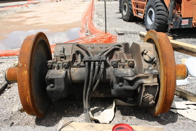
Side frames on railcars are not permanently attached to the bolster.
The span bolster has Tee shaped ends that lock into the sideframe…remove the springs, lift the side frame straight up and it will side out and away from the bolster.
The axles and the keeper clips hold the ends of the trucks together and square to each other.
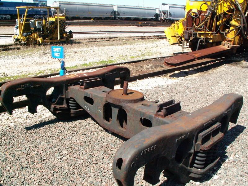
Look at the end of the bolster on the right side, just above the springs, and you can see the Tee.
There is some rigidity there, but a lot of the ridged strength comes from the solid axles too.
Solid axles also distribute the weight side to side, and some of the sideways forces.
There are axle-less designs in use in Europe, and four wheel cars too, but the loading is small compared to the US.
Such designs requite the bolster and side frame be able to absorb or transmit the lateral forces singularly, without the added strength of the axle, which makes the whole set up heavy, big and complicated.
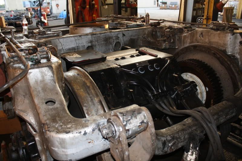
Look at the photo for a few minutes and you will see how easy it is to dissemble the whole thing…