Many of you will yawn, but we all have our different fascinations with the RR, and mine is signaling, especially when you compare it against automobile/traffic signaling. Why?
I guess the fundamental reason is that the RR signaling system is in sync with the state of the track, versus automobile signaling systems which are not in sync with the roads but are more asynchronous.
Trains (via ABS) + CTC influences the signals, and the signals influences the trains. The position of the trains further influence the CTC/RTC (if in use) which through its own set of decisions further influence the signals, which further influence the trains. It is a closed loop system. I.e. A alters B which alters C which alters A.
This is very different that automobile/traffic signal systems. They have either no or little influence from the state of the roads. Some signals are controlled by timers, and some are controlled by computers that build “timing routines” based on known volumes. If an accident happens between two signal controlled intersections and blocks the street, the signaling cycles would not #8216;pause#8217; until the street was cleared up, nor would they change (instantly) to indicate something different. For intersections that do have sensors, the sensors simply alter the timings. A green aspect at an intersection does not certify the pavement ahead is actually passable. The signals are nothing more than electronic ‘right of way’ signalers. It is an open loop system. I.e. A alters B, but B does not alter A.
As most of us know already, a RR signal system is very different. It (is supposed to) guarantees either: #1 The track block ahead is clear, and so is the one after it. #2 The track block ahead is clear, but the one after it is not. #3 The track block ahead is not clear.
It can also indicate other information, like speed for a given block or section of block, but this is sort of secondary information. (<< That comment does
I too am interested in signaling. On my last layout I built my own signal system (a small one) and your right, for the most part it is simple logic. I used 555/567 phase lock loops for track detection (powered locos only). On the simple blocks I used 7400 series logic gates. If I remember right 1 NOR gate and 1 NAND gate for each direction with Ultra bright LEDs in an enclosed box each pointed at the end of a plastic fiber optic line that ran to the signal head. This was duplicated for the other direction. For blocks that had more complex arrangements I used EPROMS (electronic programable read only memory) and each address line was assosiated with a track condition (through buffer or inverter gates) usually 4 for each track for occupancy of the blocks ahead, one for switch condition and one for holding (emulating CTC) at the absolute signals. With 8 data pins for outputs I could run 6 LEDs, 2 of each red/yellow/green for a two head signal with 2 lines to spare. I cplanned on using those two extra lines to drive 555 timers to get flashing aspects, but I never did that. I had to buy a PROM blaster and write the truth tables to use the EPROMS. It took a lot of time and effort to build the system (mostley building the signals themselves, which I still have).
The problem with that set-up was the track only had about 60 linear feet. So there was not enough blocks for it to serve a purpose. Right about the time I worked the bugs out I had to move and that layout met mr. sledghammer. That was over 10 years ago and I’ve only had one layout sience and that was even smaller. I had planned for years to use this same system on a future (and bigger) layout but after a visit to the La Mesa Tehachappi layout and seeing there pc controlled signal system that can be run as ASB or CTC, I think that is the route I will go. And I can still use all those LED / fiber optic signals I built.
you guys are way over my head technically speaking, but I really enjoy signals. I always sneak a peak at any signal I pass.
One of my favorite memories and I took a slide years ago of it was during a blinding snowstorm how a GTW searchlight signal pierced thru the snow with it’s red light. Shine on!
My feelings of signals vary a bit from yours…they communicate to me the possibility of a train being in the area. Also, I like the different types of signals…semaphores, searchlite, color position (B&O), PRR type, and the modern types, plus the dwarf signals.
Probably my favorite is color position signals and then have a dwarf signal at the end of a siding. Good stuff!
I too like signals, and I better learn em, becasue at the model railraod club my dad and I are members of, we are goig to have working signals on the layout, and we need to abide by them!!! I have some homework to do before I can run trians!!![:D][:D]
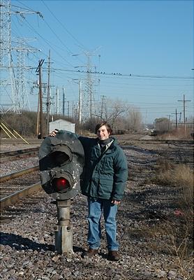
Here is a picture of me with what might just be MY favorite signal ever!!!
I agree…your coming down the track doing 100KMph, making good time, you go around that bend that you’ve gone around so many times, and there it is …the sentinel keeping watch over the next block…and its yellow…you go “hmmmm thats odd”…anyway you knock down the throttle, maybe some break, and around the next bend…sure shot…red…and about 100 feet up the rail…train ‘abc’ stopped.
My favorite is the three lamp signals…very similar looking to traffic lights…and the new LED versions are way cool…but have one problem…low heat output, and in blowing snow I have seen many of em get completly covered over…you can’t tell if the lamp is on or not.
I just might someday this coming summer, take a ride on a passenger train, and sit back in the obervation deck, and hopefully will get some good short videos of signals in action. [:)]
I didn’t get a chance to look at the devices that ran the signals at the La Mesa club. From what I gather they are tied to the PC via a serial buss, as are the track detection devices (mabee someone from the club is on these forums and can clairify). The PC that ran the whole thing was an antique (probably an 8088 CPU [:O][(-D]) with 5 1/2" floppy drives. When they are having a session there is a dispacher that runs a CTC machine that is also tied to the PC. Or the PC will run in ABS mode when they are running dureing the week.
Brian, I have all kinds of schematics in storeage up north. I could make a quick sketch of the desighn and e-mail it to you though as I remember most of the details. But there are a few things I can’t remember like the pin outs of the EPROMs chips or the frequency of the phase lock loop.
When I first started building this signal system I was going to use it as my master thesis project at ITT tech. It took a lot longer than I expected though and it was a couple years after school before I built it on the layout. Much of the circuitry was made on pref board as I never got around to etching most of the PC boards. I didn’t have enough track to do the system justice. So it was more an astetic thing and didn’t really serve a purpose for running.
Ed, I really don’t know what those rails are for. It would be a logical assumption that is what they are for though. Ya know they are triple tracking the pass. They are just getting to the bottom of the canyon right now. From what I hear they will be following this track (normaly used for uphill trains) with the third track. I wonder how they will handle this overpass (not seen but right over my head is hwy 138) as there is not enough room between the pillars for 2 tracks.
I’m not overly impressed with that site. Now this page below is an awesome resource of good signaling sites…and it does include the Signal Box too! [:)]
Just an aside for the folks that have been sending me schematics and info on their MRR signaling systems- it just occurred to me that these setups probably won’t work with DCC systems, right? DCC uses a constant AC voltage to power the locos.
Hmmm, OK, I went back and looked at your schematic- what the heck does the LM555/track detector trigger off of? Transients from the loco motors reaching a threshold as they cross the detector tie-in points?
Brian,
The 555 is a very versatile multivibrator that can be used for many timing or signal generating tasks. In my signal system I use it for two things. One is for the flashing signals, the 555 is timed for a little over one second in frequency with roughly a 50% duty cycle to match what the timeing of signal flashing is. The other use is in the track detection. The 555 is used to generate a high frequency signal. That signal is applied to one rail through a coupleing capacitor (That blocks track voltage). When a locomotive is in the block that high freq signal is coupled to the other rail. Attached through another coupleing capacitor is a 567 phase lock loop chip. This 567 PLL chip has a pin (lock) that when it senses the high frequency on the 2nd rail will provide a “high” logic state. This “high” logic state is what tells the rest of the signal logic that the block is occupied. I had to add small capacitors to all the wheelsets (locos and EOT equiped cars) to shunt the high freq signal between the rails. I can’t remember what frequency I used but I’m sure it was around 1200hz.