Look at this picture, the bracing is 45 degrees, if I understand it right, this way is the strongest:
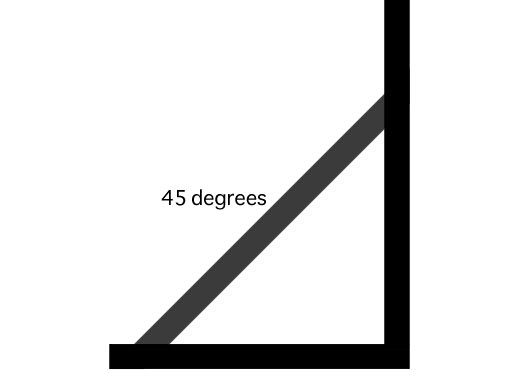
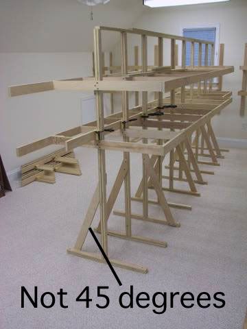
So why did they not make it 45 degrees in this picture?
Can someone please explain the formula behind this…
Look at this picture, the bracing is 45 degrees, if I understand it right, this way is the strongest:
So why did they not make it 45 degrees in this picture?
Can someone please explain the formula behind this…
Two reasons my guess.
They didn’t want to trip on it.
The higher they get up the support, the less rotational force. With two uper levels, it will tend to be top heavy.
45 degrees is strongest, but what they did was strong enough and was more convienent. For a train table, what works with the width is good enough. 20/70- would be about my minimum.
A 45 degree brace is often strongest becaust the component vectors are balanced.
Mechanics is a summing of the vectors at a point. Component vectors are the forces that act along either the X or Y axis. With any diagonal member or force, part of the action will propagate along the X axis (horixontal) and part will act along the Y axis (vertical). By reducing the each of the diagonal calculations to their constituent X and Y components, the math is greatly simplified.
However, the angle of the brace is not the only consideration. If the builders in your example had made the braces at a 45 degree angle, then the triangle described would resist higher forces at any of the triangle’s vertex points than a different configuration, but…
If the structure does not have to resist forces which threaten the wood’s or fastener’s integrity, then you can gain more stability by creating a larger triangle, because the resulting lever arm is longer.
Simply put, a 45 degree triangle will resist more overall force without deflection or failing, but a larger triangle will make the whole structure stronger, as long as the brace is not in dager of failing. In the extreme case, consider two braces. One is a 45 degree brace, which describes a triangle with two legs of 1 inch and a hypotenuse equal to the square root of two inches.
Now compare that to a brace at 70 degrees which encloses a triangle with legs of one foot and five feet. (No I didn’t check the math here, Window’s built in calculator is a pain to work with for trig.)
The tiny triangle will fail at higher load factors than the larger, but the larger triangle will resist deformation on the longer vertical leg than the tiny brace, because the long leg of the triangle in anchored further out from the right angle corner.
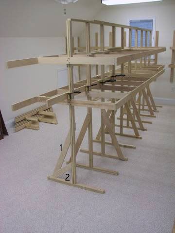
I changed the picture in Photoshop. When I look at it I get the feeling that bracing 1 is the strongest, but it’s bracing 2 that is 45 degrees. What do you guys think?
WOW, here is the solution and I can’t understand a word about what you are explaining [:D] I will read it a couple of times and see if I can understand it, thanks.
[quote]
QUOTE: Originally posted by jeffers_mz
A 45 degree brace is often strongest becaust the component vectors are balanced.
Mechanics is a summing of the vectors at a point. Component vectors are the forces that act along either the X or Y axis. With any diagonal member or force, part of the action will propagate along the X axis (horixontal) and part will act along the Y axis (vertical). By reducing the each of the diagonal calculations to their constituent X and Y components, the math is greatly simplified.
However, the angle of the brace is not the only consideration. If the builders in your example had made the braces at a 45 degree angle, then the triangle described would resist higher forces at any of the triangle’s vertex points than a different configuration, but…
If the structure does not have to resist forces which threaten the wood’s or fastener’s integrity, then you can gain more stability by creating a larger triangle, because the resulting lever arm is longer.
Simply put, a 45 degree triangle will resist more overall force without deflection or failing, but a larger triangle will make the whole structure stronger, as long as the brace is not in dager of failing. In the extreme case, consider two braces. One is a 45 degree brace, which describes a triangle with two legs of 1 inch and a hypotenuse equal to the square root of two inches.
Now compare that to a brace at 70 degrees which encloses a triangle with legs of one foot and five feet. (No I didn’t check the math here, Window’s built in calculator is a pain to work with for trig.)
The tiny triangle will fail at higher load factors than the larger, but the larger triangle will resist deformation on the longer vertical leg than the tiny brace, because the long leg of the t
jeffers_mz:
Do you mean that it’s 2 different forces in this example? And a good balance between the 2 forces is the importent thing?
Here, this should explain the reasoning:
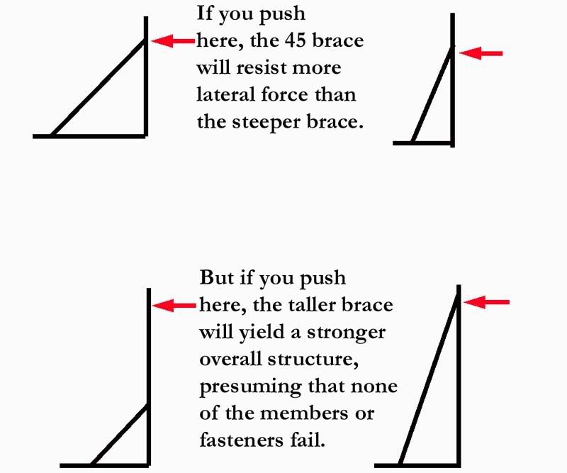
The weight and probable sway will be applied high above the brace, up where the shelves are at. As long as you don’t cut the brace too small or use fasteners which aren’t strong enough, a taller brace will resist the expected loads better than the shorter brace.
This was much easier to understand. Thanks for your excellent answer.
Your original post asked two questions, and it is important to keep the two answers seperate.
This diagram goes deeper into both questions than my last post:
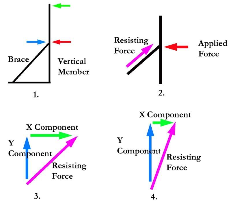
In figure one, a force applied like the red arrow will put the brace into compression, i.e. try make the brace shorter. A force applied like the blue arrow will put the brace into tension, i.e. make it longer. A force applied like the green arrow will put the brace into compression, just like the red arrow, but will also put the vertical member into torsion, i.e. apply a bending moment, a rotational force that will either bend the vertical member or cause the entire structure to rotate, or both. This would make the vertical member into a lever arm.
In figure 2, only a force applied like the the red arrow is examined. The red arrow force pushes against the structure, and by Newton’s law, the equal and opposite reaction is for the brace to push back, a reactive force.
In figure 3, the reactive force is seperated into two component forces, just like we can seperate the quantity four into two component quantities, three and one. This is done to simplify the math, since only the X component of the reactive force will resist the original red arrow force. By seperating the reactive force into X and Y components, we can measure and compare the original (red arrow)push, versus the brace’s resistence to the original push (purple arrow), since only the X component of the purple arrow will resist the red arrow, which only acts in the horizontal direction.
Trigonome
jeffers_mz:
Outstanding answer to my questions. You are really good. I’m sure other users will learn a lot as well from your excellent answer and ‘easy to understand’ pictures.
Physics is kewl, ain’t it?
![]()
All the above applies to static forces, steady forces pushing against steady resistence.
When forces change over time, “dynamics”, like when a moving train rolls onto and off of a bridge, the math gets a lot uglier (more complex, but still just as elegant). The whole truss, and every member in it, become “springs”, compressing, stretching, and bending, all involved in a coordinated ballet of interaction, resistence and resultant vectors. That’s where calculus comes into play. The ability to define the slope of a curve on a graph at a given point, (differential calculus) or the ability to quantify the area under a curve on a graph (integral calculus) or, heaven forbid, the area between two different curves is required to solve these more complex design questions.
Yep, the math hurts my head too, but the satisfaction of being able to assign hard numbers to this kind of question, then apply the answer and have it result in a broidge that takes the load and remains standing is worth all the pain the math can dish out.
You should consider taking a class in statics and dynamics sometime. Your questions indicate that you have a feel for it. To me, this is even more fascinating than the physics itself. Many of the other contributors to this thread may fit into this category too, maybe not able to handle the actual math, (hard to tell since those able have simplified their answers) but having an instinctive feel for how mechanics operate anyway.
The power that results from taking an instinctive feel for mechanics and developing it into an ability to actually calculate numerical solutions truly illustrates the adage:
“Give me a long enough lever and a place to stand, and I will move the earth.”
…or the sun…or…
![]()
The principles involved actually carry over into economics, politics, social questions, military maneuver, etc, if properly applied. For example,
It is an excellent answer, and to make it perhaps more realistic, in the literal sense, imagine that your legs form the sides of a triangle. If you were in a very strong wind coming from one side of your body, would you stand with your legs close together, or would you brace yourself by widening your stance? You’d spread your feet by about 40cm in order to counter the wind’s wanting to make your upper body move with it. You would spread your legs even more if the wind increased in velocity, and this is untuitive.
The bracing in your first diagram is sufficient for the “wind” of instability that the weight on the shelving will duplicate on the one side of the bench. Since your bench has the shelving on one side only, the bench will want to rotate in that direction, but pivoting from its “foot”. The more vertical bracing counters that satisfactorily, but it also doesn’t impose itself into the footpath of the operators.
Shure is and, shure brings back memories…
Should we should start to call you Newton? Sounds better than Galelio.
Bob K.
The key factor is the triangular shape. As long as the fasteners hold and the structural members don’t break, it is impossible to distort a triangle. Any other shape is less stable. Rectangles become parallelograms, which is why bridge builders put one or more diagonal braces in a rectangular panel.
45 degrees is the strongest brace angle for a right-angle triangle, but the absolutely strongest is an equilateral triangle with three 60 degree angles. Not very practical for table building, though.
Chuck
If the builder was supporting people, he would probably have done it at 45 degrees, but supporting trains and scenery(as long as its not to heavy the angle will work. just my 2 cents
you also reach an equilibrium of force using a 45 degree angle…if you look at a protractor, there are degrees from 0 to 90 that make a right angle…since 45 degrees is exactly half the distance beteen 0 and 90 the forces exerted on either side of the 90 degree angle will counter balance with each side of the 45 degree angle…hence it’s at the strongest point using a 45 degree angle…chuck
The bench work on the images dont look too sturdy. Almost as if you breath on them they will fall over. I think they are wanting to put this against a wall or something.
And I was just going to watch…
So tomikawaTT, pray tell how do you figure a 30, 60, 90 is THE strongest shape?
P. S. - it ain’t.
having taken static and dynamics courses, I understand the answer, you explained it better than I ever could have. But angles of moment are confusing if you have never taken the courses. (trig) Great explanation. But refering to the photos you asked about, getting the supports out to the edges of the table and to the floor where they have it spreads the forces (weight) as well as can be expected consideing what they are trying to build. My tables are basically the same (against the wall of course.)