Well, after a brief hiatus on construction of the layout, I’m ready to go again. I have 90% of my Atlas track weather, layed, corked, etc. and now am ready to put on the finishing touches, like switch machines and ballast.
Ok, so I got a couple of switch machines (Tortoise), and I have one mounted already. I’m using 3m Dual Lock with great results to mount, and a bit heavier guage wire cut to fit. Now what? I see that Circuitron makes an easier wire connector so you don’t have to solder the wires to the bottom, and I will get those, but what do I connect? A throw switch to move the machine and a power source?
Also, for example, my yard has about 8-10 switches. Do I just wire them all up to one another and then to one power source? And if so, what size powerpack should I get to handle that many?
The wiring diagram that comes with the Tortoise is pretty good, actually.
You’ll want a DPDT toggle switch for each turnout. You can wire all of them to one power supply, but make sure you do so in parallel, not serial. I recommend buying a cheap 12v DC power supply for this purpose rather than using a power pack.
The two outside lands (solder areas) are the power connectors. The other 6 lands are the two double pole switches used for what ever you need. The switches can control lights, frog power, etc.
Each Tortise draws about 20 milliamps maximum (.020 amps). So you can use a single power source up to 12 vdc to handle all of your Tortise machines.
A one Amp power source can easily support 40 Tortise machines.
The instruction sheet that comes with each Tortise clearly shows how to connect the machines, including the use of LED’s in series with each Tortise.
I like to get the torti completely wired and mounted before I put it on the layout. I use both SPDT Toggles built into the torti to power the frog since I do not control any lighting with them. I am using DCC so there could be up to 5 amps of power going through those toggles which are rated for 2 amps for a short time if a short occurs at the frog.
I mount the tortiose on a short piece of 1/4" pine (other materials work just as well). Wire the Tortiose as shown to a 6 position terminal strip. Wires solder to the leads on the machine very easily.
I pull power directly from a bus terminal to power the toggles that go to the frog.
You can also adapt the tortiose for use in special areas. Here I have several machines mounted behind where the backdrop will go. I can get them easily if nessesary and there is no room as staging is directly under where the turnouts are. I used some old code 100 rail and piano wire to conect the torti to the turnout.
The terminal strips make hook up a breeze and are cheaper than the plug on wire mounts made by circuitron. All in all the tortiose machine is the most forgiving and easy to use switch machine I have ever used. I will have over 60 of them on my layout by the time I am finished.
BTW I am using 9V 300 mA to 500 mA wall warts to power them. The movement of the machines is very prototypical at that voltage and on wall wart can supply power to at least 15 machines at 9v. (I have one area that I am doing this with no problem.)
Hello “NYC,” Here’s my advice, as recently posted in another thread on this forum: I build my own power supplies for Tortoise motors, using the circuit from the article “Using slow-motion switch motors” in the August 1987 “Model Railroader,” pages 62-65. (Photocopies available from the “Shop” section of this Web site, or by e-mail to customerservice@kalmbach.com.) This is a polarized supply delivering + and -12VDC with filter capacitors to eliminate motor hum. I run a three-wire bus around the layout (+, -, and ground) and control the motors with SPDT switches. I’ll add that this supply can easily power 20 or more Tortoise motors. I don’t bother with edge connectors. It’s easy to push wires through the back of the Circuitron circuit board, solder them on the front, and trim them down to the solder “tent.” I don’t see the need for quick disconnect connectors since I’ve never had a Tortoise fail, and you’lll still need to solder wires to the connector. So long, Andy
First you will need DPDT toggle switches - one per torti: part # 275-666
22 guage wire such as: Radio Shack part # 278-1224
Wall Wart(s) 9v # 273-1770 or 12v # 273-1773
If you want to use Terminal strips, # 274-659 (6 position) or # 274-660 (8 position). If you are not using the built in SPDT toggles in the tortiose then you could use: #274-656 (2 position)
Thanks everyone for your help…It’s people like you that make this hobby even more fun and enjoyable, and not so difficult and frustrating that you end up pulling your hair out.
Hopefully, soon I will have the track all wired up and ready to go…
heh… well, for what it’s worth, I went with manual throws from Caboose Industries for my layout. No wiring, and there’s something satisfying about throwing the turnout by hand. It’s just sort of “railroady” if you get my drift…
Thanks for everyones help. I stopped by Radioshack and got all I needed, and I just got my first machine soldered, wired, and working. The tortoise is a cool feature to have…
I got the 12V 1 amp “wall wart” at radio shack for the switch machines. Now, what do I do with it? Do I just strip the wires and connect them to a terminal, or is there a certain adaptor plug or something I should get?
Your ‘wall wart’ should do you fine. However, should you ever find you push its limits - which is easier to do than you might think if you start doing a yard with tortii, using LEDs in control panels, and certainly if you start powering other 12v stuff with it… I am a great fan of this little power supply:
At $20, it’s certainly more than a wallwart. But it has 2amps output and you can modify the voltage. I like to be able to turn the voltage DOWN from 12v which makes the tortoise run even slower and quieter. I rather like to get my “throw” time down to 2-3 seconds rather than the standard 1 second.
I have ~100 tortoise machines and about 300 bicolor LEDs on the control panels for them (I use multiple toggles to control some of them from various locations, thus the “extra” LEDs). I only recently had to get a second one of these to keep up.
While you are wiring them, you might want to include (or plan for) lights to show which way the switch is thrown. Or you could simply use the toggle switch itself.
The easiest way to get indicator lights is to put 2 LEDs in series with the power feed. For example, in howmus’ diagram put a red LED between #3 and the Tortoise. Put a green LED between #4 and the Tortoise. If the LED does not light up when it should, turn it around 180-degrees (reverse the polarity).
These lights could be on a control panel or on trackside signals.
Any suggestion on LED type, size, etc? Also, would it be possible to light both a red and green coming off both leads to the tortise so you could have one direction lit green with the other red, or better yet, do they make bicolored LEDs?
One more comment: Howmus, I like the idea of the terminal strip below each tortoise to go directly to it and then to the switches on the control panel, very clean wiring idea, I hadn’t thought of that. I use them for areas between sections, on the control panel and other locals but hadn’t thought of using it at the base of the Tortoise.
Thank You, sir! BTW, you will find that there is a mirad of different ways to run panel lights off the torti set up. I don’t presently use them (although they may be put in at a latter time) so I can’t comment on them. There have been threads devoted to that issue here. Try a search on it and see if anything comes up. You may find some helpful information.
Yes, they make bicolor red/green LED’s that change color depending on polarity.
What I do is hook two of them up in opposite (i.e. long lead to long lead or short lead to short lead) so that one is always red and one always green. Then it’s simply a matter of wiring them between your toggles and tortoise and installing them in the control panel. Now you’ll always have one path green and one red. I wire all my toggles, tortoises, etc. identically, so I know everything will synch up, but even if the LED’s don’t synch to the actual turnout position, you just flip around the connection to the #1 and #8 terminal on the tortoise and they do.
That last bit, incidentally, is another reason I’m sold on the edge connectors. I can just hook up the whole works, and if the LED’s and actual turnout are out of synch, I pull the connector off, turn it around and stick it back on…
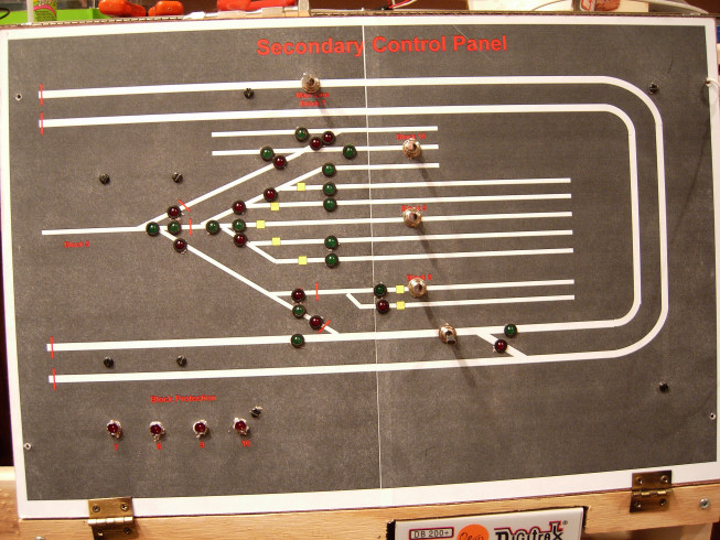
I’ve taken the approach of rolling my own panels. I am just finishing the second one. I make mine 11"x17" but any size will work. The reason for 11"x17" is that I use 8.5"x11" full sheet label paper and draw the panel using Visio and then print it on a printer. 11"x17" takes two sheets. Here’s a sample:
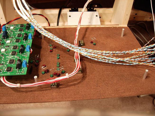
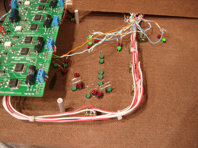
The LEDs and switches all mount in 1/4" holes. The yellow squares depict decoupler magnets. The toggle switches are for block power and the red lines indicate insulated joiners. Here’s the backside under construction with the power sheild on standoffs.
The block power is all wired at this point and the Cat5 cables are for the switch machines. I use Cat5 cabling and 66 blocks to bring all of the Tortoise wiring in:
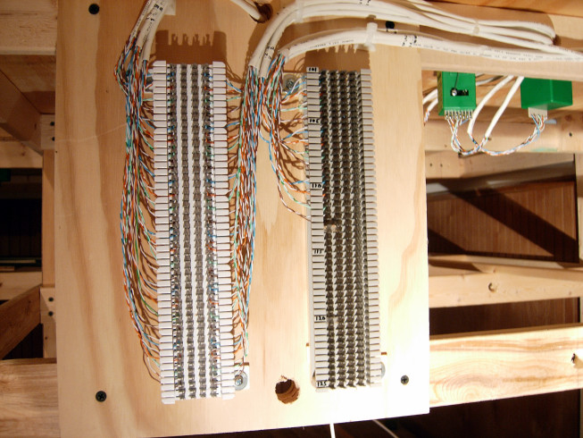
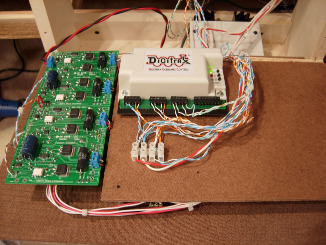
Then I run Cat5 cables to the control panel (as shown in the second picture not yet terminated). I’ve decide to use DS54s to control the Tortoises instead of switches but the concept is the same. The only different is that the DS54s mount on another piece of hardboard on standoffs, instead if using toggle switches on the panel. My primary panel uses toggle switches. Here one of the DS64s mounted:
The panel is upside down in this picture. The advantage of the 66 blocks is that changing wiring is just pulling the Cat5 off and punching it down again.
Here’s a couple of pictures with further progress. One of the DS64s is wired. I have two more coming from Litchfield Station. They are in very short supply from Digitrax. I’ll finish tidying up the wiring with tie wraps once all three are installed.