Or eliminate the 4 diodes on the left and use a 12-16V DC power supply of at least 2 amps. The - of the power supply would go to the - of all the rest along the bottom. Don’t mix that up, the big capacitor is polarized and they go boom when hooked up the wrong way. Literally. Use one at the top end of the specs - closer to 4700uF than 2200uF, the bigger the cap the more oomph the circuit has, and the more simulataneous switch machines it can operate. Don;t go over 4700 though, it may overload the transistor.
I wish I had my book handy, the one I built years ago sure looked like that one, but I could swear I powered it fromt he AC terminals of my old train set power pack when I got the MRC Tech II to run the trains. But my CD supply did not have the diodes in it, and that would be impossible to run on AC, it would fry the transistor if not the capacitor. It mayhave just has a single diode ont he input side. I know where the book is, just have to dig it out and look. I don;t have the unit, and youw ouldn;t want to see it - I simply connected allt he parts together with no perf board and soldered them together, hanging off the transistor (which I put in a heat sink). If I find it I can post all the Radio SHack part numbers for the pieces you need. Pretty sure it’s all available fromt here still, even thought hey cut back on parts lately. It would eb cheaper from oen of the suppliers like Mouser but til you add in shipping and stuff… If you were building a dozen of them I’d advise getting parts from somewhere OTHER than Radio Shack, but for just one, it’s all there.
Might go the DC route since we’ve got more of those laying around here. Actually might have some parts around too like a DC jack… Good thing I’ve sort of got a grasp on electronics too, I’ve played about with building/modding guitar effects (so I’ve also got perfboard around too!) I’ll write up a parts list and stop down to Radio Shack and build one I think. Just one question I still have, the right side of the circuit those + and - leads (the input/output parts, maybe?) do those go on to connect to my first Atlas switch control box?
The output polarity does not matter, just connect the + to one side screw ont he Atlas boxes and the - to the other. It won’t matter.
It DOES need a fairly hefty input supply, there is a bit of a surge as the transistor allows the cap to recharge. Wall warts usually have a fusible link in them so if you try to use a low power one (typical 500ma wall wart) it might blow that fusible link. I know using my old train set pack to power mine you could definitely tell when you let go of the turnout pushbutton and it recharged - but trains et power packs usually handle a short term overload without tripping. I’ll find my book and get specifics.
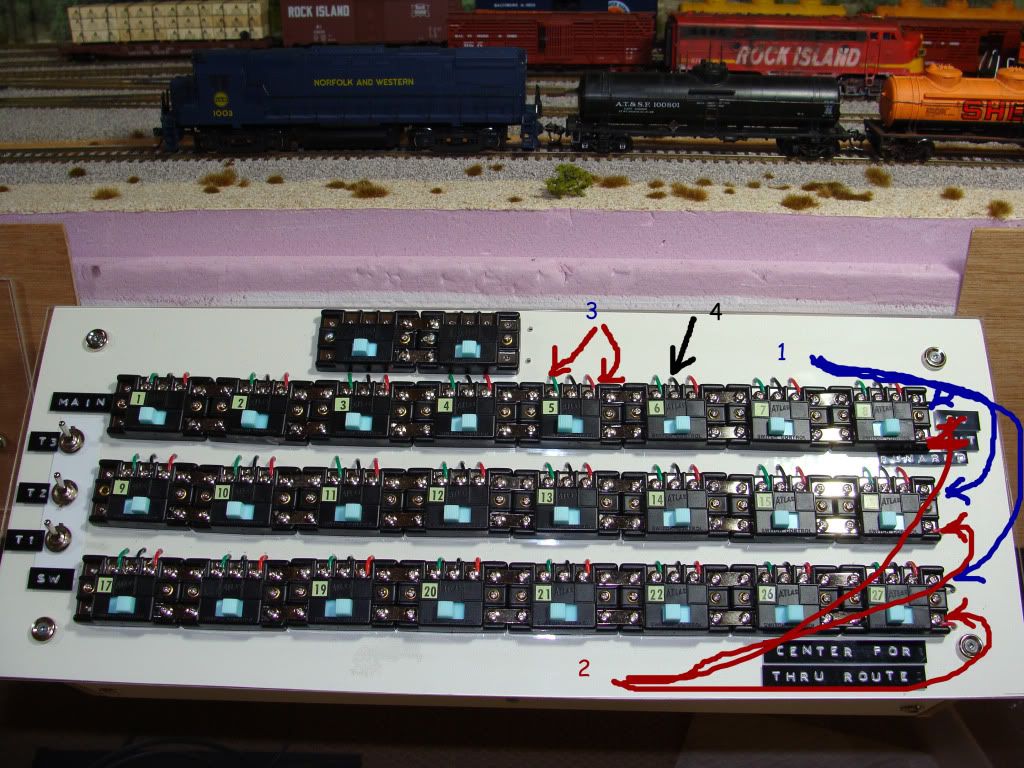
Chessie, I think this is what you are also asking. Now that you have the idea of making or buying a capacitor discharge circuit, you wanted to see how to wire up the Atlas switch controllers to the wires coming from the Atlas snap switch machines.
Below are photos of one of my control boxes. Even if just using a few switches, the connections pattern is the same of course.
(Blue) Wires from one terminal of the control (doesn’t matter which) are connected to one of the leads coming in from the cap. discharge (doesn’t matter which) Here you can see the controls are made with connectors to make gang connections.
2 (Red) Wires from the other terminal of the control are connected to the remaining input lead from the cap discharge.
Wires from each switch side of the controller are run on out to the layout to connect with the red and green wires coming from the Atlas switch machines. It is best to use red and green wire to keep colours matched.
(Black) common wire does not need to go out to each machine. This is connected to a single terminal block in this control box and a single black common wire comes in from the layout. To this latter single wire, all the black common wires from the individual switch machines are connected somewhere on the layout through several other terminal strips. In other words, you do not need to run three wires from every switch machine back to the control area…just the red and green and gang up the common black out on the layout. This makes wiring a little simpler.
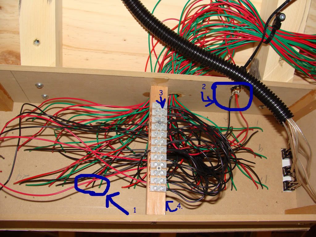
UNDERSIDE
Three wires from each control. Each black one goes to one side of terminal strip which has been modified with copper wire
You really want the frist and second page of that forum. If you need the pics i downloaded them and can send them to you. This capacitor will fire off about 2 or 3 switches at once. In less than a second it recharges. I was reading this forum and tried to build this one http://home.cogeco.ca/~rpaisley4/CDPSU.html that was recommended, but it didn’t work. The one I built from the first web site, that was really snaps the tracks. I love it.
I built the one in B on Rob Paisley’s page way back in 1978 (there was no web back then - but the same simple circuit was in Peter Thorne’s Practical Electronic Projects for Model Railroaders from Kalmbach). That’s about a simple a one you can make with the fast recharge. Far as I know it still works, but I haven’t used solenoid switch motors since, well, that layout that I used the CDU on way back then.