Hey everyone, I have some Atlas code 83 switches on my layout that I have electric Atlas switch machines for but I haven’t wired them up yet. They are all about 4’ away from where the switch controls are. I’ve been wondering how I should wire these up: stranded or solid wire? What gauge? How long should I leave the wires coming from the switch machine? Should I solder the connections or somehow solderlessly connect them? Also, what should I use to power the machines? Thanks!
If you don’t want to solder, get some terminal strips, the kind with two rows of screws. Usully you can;t get ones that are 3 position, it’s 2 or 4. Run the wires under the layout, near the machoine mount the terminal strip. Cut back the wires, and attach them tot he screws on one side. FOr runnign back to the control panel. anything about 22 gauge or heavier will work. Stranded or solid doesn’t really matter. Using 3 conductor wire is easier, since it’s already bundled. If the colors don;t exactly match the 3 colors Atlas uses, come up with a system and stick with it.
–Randy
I went to Home Depot and bought a hundred-foot roll of telephone wire, two pair, which gives me four conductors. It’s about #24 or #26, which is fine for switch machines. I solder the connections and use heat-shrink tubing to insulate the joints. Face it. If you’re going to be a model railroader, you’re going to have to solder stuff. This is one of the easier things to solder.
Consider how you’re going to route your wires. You can go straight point-to-point across the layout from the turnout to the control panel, but you may want to consider doing it more systematically and running the wires through common wire runs for neatness and maintainability.
For twin-coil switch machines like Atlas an Peco, get a capacitive discharge (CD) circuit. You can build one yourself and drive it with an old train transformer, or you can buy a unit with a power supply built in. A CD circuit gives you a much stronger “kick” to throw the machines, which helps when you’ve got long wire runs or tougher machines like Pecos. It also protects the switch machines if the toggle on your control panel sticks.
- stranded or solid - doesn’t matter.
- what gauge - bell wire is fine (I think bell wire is #26 gauge)
- how long should I leave the wires - There are three wires. I would leave them the easiest length that they are to work with. I would also leave them three slilghtly different lengths so that the connections aren’t right together.
- solder or other connection - for tiny wires I prefer soldering covered with heat shrink tubing. Small wire nuts would probably work as well.
- what power - theoretically they are to be operated off the AC accessory output from the power pack. I would not recommend that, unless you get a second one just for that purpose.
I second the idea of getting or building a capacitor discharge unit. Circuitron’s Snapper is a good unit or there are plans out there to build your own with easily available parts. Telephone wire is good for using to operate the machines. The Red, Green and Black wires match the colors the manufacturers use and the Yellow will be a spare. I prefer stranded wire. With solid wire be careful you do not nick the wire while stripping the insulation. It will weaken the wire and will cause it to break if the wire is moved. If you are using the Atlas controllers there is no need to solder the wires. Loop the wire around the screws and tighten. The telephone wire is good for any length of run you will need especially if you use a CD unit.
http://www.allelectronics.com/make-a-store/item/TS-323/3-POSITION-DUAL-ROW-TERMINAL-STRIP-10A/1.html
I went that route. Built 7 Capacitor discharge circuits and mount them near each switch. I wire the switch end of the circuits to terminal strips (then from strips to switch machines), and then use Cat-5 from the circuit to my control panel. I put Ethernet jacks on the ends of the Cat-5 so if I need to change my panel I just disconnect the jacks.
They work great 99% of the time, but were a pain to build.
retsignalmtr:
They work great 99% of the time, but were a pain to build.
Hey [:D]
I couldn’t help but wonder why you needed 7 CDCs?
I built one for less than $10. and it throws my double turnouts with no problem. It would probably power several more at one time. I built mine to run on 120V and puts out 30V for a split second. It only takes 1/2 second to recharge. I used three wire, bell wire. It didn’t cost much.
Cheers [tup]
Lee
And if it’s because of lots of turnotus to throw, there’s a slightly fancier version that uses a power transistor to control the recharge of what can be a VERY large capcitor that shoudl eb able to throw a half dozen or more of the old heavy duty twin coil machines all at once - and a dozen Atlas ones at least. It was one liek this that I actually built even though it was probably overkill for my N scale layout with a grand total of 6 turnouts on it. It looks like a mess, the transistor is on a heat sink and the rest of the parts just hang off it, but it worked, and as far as I know still works although it’s been stored away for 30 years now. My circuit came from Peter THorne’s Practical Electronic Projects for Model Railroaders, but there’s a nearly identical one on Rob Paisley’s site.
–Randy
Thanks for everyone’s replies, I’ll look into building one of those. I found some telephone wire that has four different wires, so I’ll use that and just leave the fourth wire unused. I’ve got an extra power pack I could use to power the switches but I’d like to avoid using a lot of space on my control panel. I’ve heard some people use regular old adapters one would use for powering things like air mattress pumps, guitar effect pedals, some DCC systems, etc. Would this work too?
Nothing says the extra power pack has to take space in the control panel area. It can be put anywhere and just run the wires to the control panel.
Yes, as long as the voltage is a match. Any electricity will run a twin coil switch machine. Over voltage will melt down the plastic on the switch motors and eventually ruin the coils as well.
If you are using the Atlas turnout motors I strongly suggest you use a capacitor discharge circuit, because if you don’t, holding the switch too long will burn out motors. I went thru 2 or 3 motors before building my CDC and none after installing it.
Good luck. [tup]
Lee
The circuit I used was designed for each turnout. Ken Stapleton designed the circuit, and actually sells kits where you can build your own, as well completely assembled kits. I built my own using his design, but next time I’ll save myself the trouble and just buy completed kits.
The CD circuits look like they would work well for me and would save a bunch of space on my control panel, plus I now know where I could store a power pack to power them. The only setback is money… Does anyone have a schematic I could use to build them myself? It might be cheaper that way…
Here is a link to a site that gives schematics for a couple of CD circuits.
http://home.cogeco.ca/~rpaisley4/CDPSU.html
Joe
Thanks Joe, I’m assuming I want circuit B on the first picture? However it doesn’t show any switches or values for anything in the circuit, correct me if I’m wrong. Also, I’m not sure how the three wires from the switch machine hook up to that? Sorry for all my questions, I’m young, but not new to the hobby, just new to doing it right! [:P]
Following the good advice on this forum I bought a discharge unit. Here is a picture of my Circuitron Snapper (just taped to the frame with electricians tape). I modified it with two jacks in place of solder pins so it would accept two regular 3.5mm inline plugs. These go to my switch control stations which are separated by 25+ feet. And another jack to accept a regular power adapter input. Now I can unplug this if I should need to.
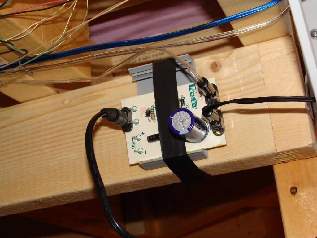
So, having more money than brains (in this case and generally with electronics) I bought this unit and had it in place many days earlier than if I had tried to make some…especially if I thought I needed to make 7 or so discharge units…which seems odd, but I am no expert.
And with a 12VAC power source just like the one for my Zephyr controller it fires over 48 switches most of which are connected with phone wire connected to the little switch wires.
Looks nice Crisco Kid, and sounds like it works well for you, which is great. However… I have far less money than brains and a decent understanding of electronics so I feel if I was to build a CD circuit I’d benefit from it more than having to buy it. Plus I only have 5 switches to control electronically so I don’t need anything large or fancy, I’m just looking for safe electronic switching. [:D] I appreciate it though, and once I move onto a bigger, better layout I’ll definitely consider your solution.
You want B, but if you scroll down the page a little bit you’ll see a schematic that looks like B at the top (plus the 4 diodes for a full wave rectifier) only it specifies component values and types so you can actually build it and have a chance of it working. Very simple project. Not very fussy about keeping short wire runs, so don;t try to build it as small as you can, leave yourself plenty of room and use short bits of wire to interconnect components if needed. Use a small perfboard from Radio Shack to assemble it on.
–Randy
–Randy
Ahh I think I understand now. So I’d build that, plug a “wall wart” into the end with 16VAC then run the + and
- ends to the Atlas switch controls?