Gary,
That link is kaput. Can you provide a good one?
Thanks!
Gary,
That link is kaput. Can you provide a good one?
Thanks!
I think we ran off another newbie
Terry,
Where can we purchase that electically conductive adhesive?
What I meant was if the plastic deforms and curls up it’s a problem. I had to file some down and they don’t look as good.
.
Access will be easier to the wing rail. I am all for making my jobs easier. If the turnout is more or less parallel to the layout edge the outside of one wing rail will be out of view and perfect for soldering a lead wire onto.
.
Also, maintenance and repair will be near-impossible if the wire is soldered to the bottom of the frog.
.
-Kevin
.
.
It is never really necessary.
.
My brass steamers pick up power from one side of the tender. That is only 4 33 inch wheels going through less than perfect contact points to maintain continuity. Crossing an insulated fromon a #6 or #8 turnout takes two of the wheels, half of the contact surface, out of the equasion.
.
An 0-6-0 only picks up power from one rail on three closely spaced small diameter drivers.
.
Powering the frogs makes my steamers more reliable.
.
Dr. Wayne has gone through the effort to add pickup to the insulated drivers and tender wheels on his brass steamers. I have no plans for that extended effort unless it proves itself necessary.
.
Powering the frogs is my go-to preference for good pick-up.
.
-Kevin
.
Kevin
Thanks - a good tip for simplicity’s sake.
Are you saying that a feeder wire soldered to a wing rail will power the frog, even though on the Walthers/Shinohara DCC-friendly turnouts they’re insulated from each other? [:^)]
Kevin,
Thanks! And I plan to do so for the same reason: to keep 'ol Murphy from putting in an appearance.
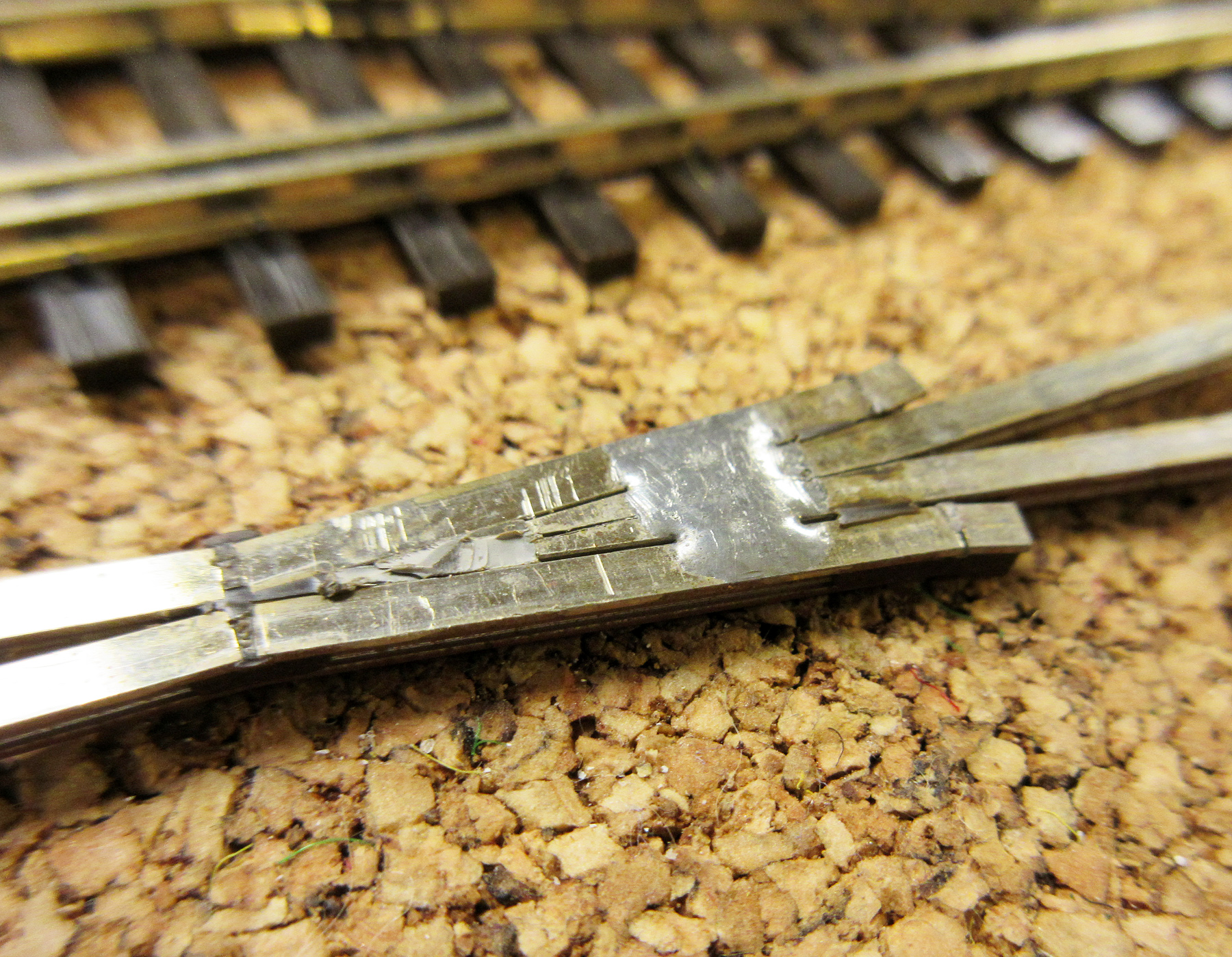
Here’s the bottom of a Shinohara/Walthers code 83 frog after the plastic has been removed:
I’m not sure what you mean by “insulated from eachother”?
The frog point and wing rails are electrically continuous through that blob of solder. I have over a hundred powered frogs with the wire soldered to the wing rail on the back side as Kevin describes.
Good Luck, Ed
Ed,
Thanks for the clarification. I didn’t look closely enough at that blob of solder in the photo before to see the electrical connection between frog and wings.
I was just looking at the frog and wing rails of my turnout from the top only (not having cut away at the plastic piece underneath), referring to the plastic strips between the wing rails and the frog visible from that top-view perspective.
One doesn’t have to remove the plastic and add a blob of solder. Frog and wing rails are already electrically continuous. (Trust me-I have a slew of them. If in doubt, check it yourself with a meter,)
Dante
Soldering to the wing rail on WS switch frogs works fine. All of mine are like this. Once painted and ballasted the feeder is not noticable at all.

That’s my plan then!