I am getting ready to lay several Walthers code 83 HO turnouts on my layout. They have insulated frogs and will be controlled by Tortoise switch machines. I want to power the frog on these turnouts. I flipped one over and there is plastic tie material over the center of the frog. I prefer to wire my switches from underneath. I scraped away that little bit of plastic and exposed the center of the frog which has a small piece of insulating plastic between the metal diverging rails. 1. Can I solder my power bus here to power the frog and should my feeder bridge the small insulator and connect to both frog rails or just connect to either side of the metal to power the frog?
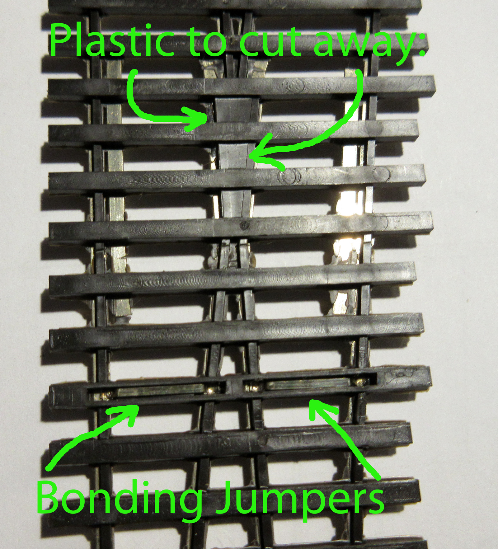
The guard rails on my Walthers DCC friendly turnouts are electrically connected with the frog. I successfully connected the frog feeders to a guardrail just as I did the other track feeders to the track rails.
I did the same thing as Dante using maybe 20 or 24 gauge wire. I used small aluminum heat sink clamps and soldered in a place where there wouldn’t be any interference with wheels passing through frog. Preferably on the “back” side away from view.
I think what you exposed on the very bottom is where the rails cross over beneath the frog so the closure rail and frog rail are connected past the frog. The a layer of plastic, then the other closure rail to other frog rail, then there is probably yet another layer fo plastic and THEN the frog. I’d try as above, rather than attaching to what you just exposed - you can verify by using a meter on continuity and seeing if the bottom exposed metal is the same as the frog, ot one of the closure rails. My money is on it being the closure rail.
Thanks to all for the replies. Will double check the continuity on the guard rails. As you say, they are easier to solder to than the cutting away the plastic. Appreciate the quick response.
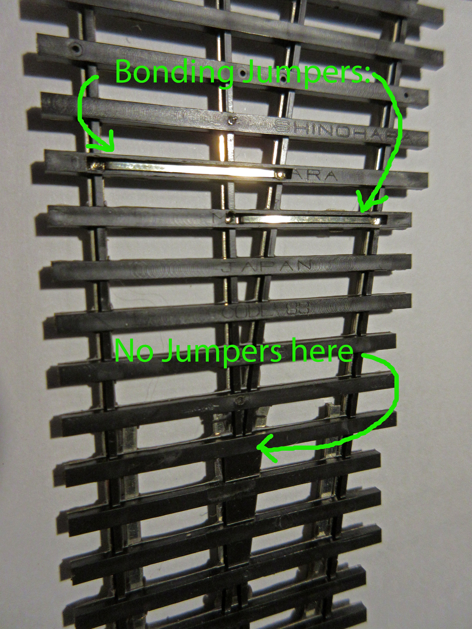
Just an update. The new Walther’s turnouts have the frog completely insulated and there is no continuity between the guard rails and the frog. However, where I scraped away the insulation from the underside “X” portion of the frog there is continuity between the two sides, so the frog power does have to solder to the frog on these turnouts.
I’d like to see that picture. There is a sticky on how to post pictures, whatever you did, didn’t work.
My Walthers turnouts are 3 years old and the guard rail is in continuity with the frog.
Since you don’t post that often (not a judgement) you may not know that Shinohara, that makes those turnouts decided to close up shop, supposedly because the owner wanted to retire and no one wanted to take over the busines…
And my newest turnout is 18 months old with continuity between guardrail and frog. Hard to believe they would change this configuration. For what purpose? Suggest you check again for continuity.
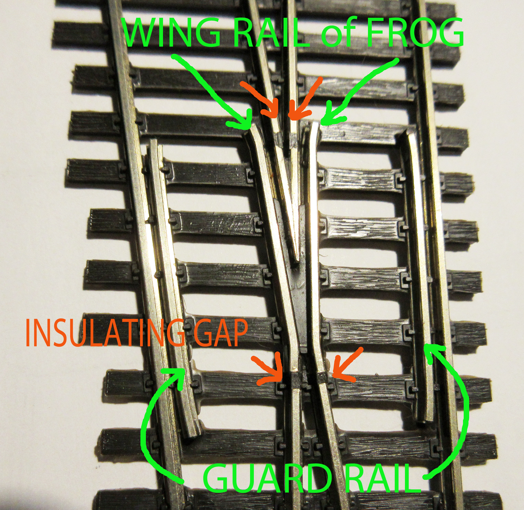
In my understanding of the terminology, the guard rails are not any part of the frog but are on the opposite rails (the stock rails) and the guide rails at the frog are called wing rails. Yes, the guard rails SHOULD be insulated from the frog.
In the injection molding process, hot plastic will seep into some of the cavity of the frog. The only “true” insulating points are at the four orange arrows.
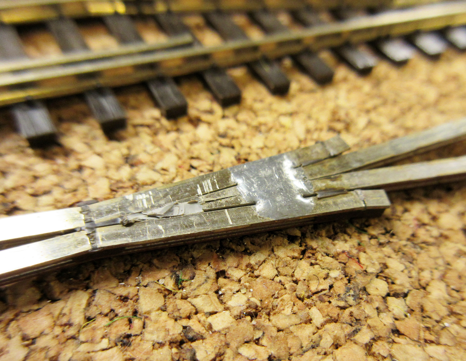
Here’s a frog I pried the plastic off of. You can see bits of the remaining plastic and the blob of solder holding everything together.
Be careful adding heat to the factory solder but, yes, a small gauge wire can be soldered there after scraping some of the plastic from the bottom. The plastic is thinner between ties at this point.
I’ve powered many-a-frog by removing the plastic from the underside and soldering in a wire, as described here by others.
Once in a while I noticed that the plastic expanded in the flangeway, making it too shallow, and becoming a potential cause of derailments. While this could be a manufacturers defect, I suspect that I got too heavy-handed with the soldering iron from time to time.
Its an easy fix, by running a small file though the flangeway and checking it with the NMRA standards gage.
The plastic on the top side of the frog is what the wheel flanges ride on. If this melts wheels can derail. I put a wet towel underneath when I soldered feeders, plus heatsinks, but some still melted.
I now drill & tap for a screw to hold the wire, or use electrically conductive adhesive.
It sounds like a “flangeway” is being described here. If so, on my Shinohara switches, the flange does NOT ride on the bottom of the flangeway because there is approximately .015" gap between the bottom of an RP25 flange and the top of the flangeway.
I have been considering adding a .015" shim in the bottom to lessen the wheel drop at this point.
Ed
PS: As mentioned by others, I too have soldered a feeder to the insulated metal frog. I used a resistance soldering machine, and with some practice, you are in and out before significant heat damage.
I only plan to use “DCC Friendly” turnouts where the turnouts go frog-to-frog like on a crossover. These places power routing would not be advantageous.
.
My intention was to solder the feeder wire to the back side of the wing rail where it cannot be seen.
Just when and why is it necessary to power the frogs, if at all? Not just recommended, but necessary.
From what I’ve read so far elsewhere, I understand that powering the frogs is recommended to maintain continuity of electrical contact and to prevent short circuits when locos cross a turnout.
I recently purchased the DCC-friendly Walthers (all-live, e.g, electrically the same as Atlas Snap Switch turnouts) turnouts for my DC-powered HO layout.
On a previous layout of the same, small size (7’ x 5’) using Atlas Snap Switch (also all-live) turnouts, I never experienced an electrical problem with the turnouts.
So, powering the frogs on new Walthers turnouts: at all necessary - or even recommended?
Short circuits are not prevented by powering frogs and are caused by other issues.
I’m having trouble with the use of the term “all live” Snap switches have plastic frogs that cannot ever be powered. Walthers DCC friend turnouts have frogs that can be powered by only if you do something to them.
Your understanding of wheelbase is backwards. If you had an SD-9, there are 3 axles on each truck. Chances are at least one wheel set of one truck will be on powered track*,* with an unpowered frog, at all times, while the other truck will be fully engaged. With a GP-9 and 2 axles per truck, maybe only 2 axles on one truck will be powered if it is a #8, maybe even a #6 or one of the curved turnouts. Those frogs are really long.
I have no knowledge of how a 2-8-0 power pickup works. I will take your word for it, even though I suspect it gets power from the tender as well.
My Bachmann 45 tonner can navigate #4 and #5 Walthers turnouts even though I went to the trouble of attaching an unpowered feeder to the frogs. It seemed to me to be easier to do at installation, than down the road after ballasting. Maybe when I install sound in that loco, my opinion will change. For now the feeders are just dangling. I have Atlas curved turnouts for future expansion, and there will only be one axle on powered rail. I will be powering those frogs.
Keep alives eliminate the need for powered frogs for the locos. I have no firm knowledge of how lighted passenger cars and cabooses behave. Other unpowered rolling stock doesn’t care about frog power.
Please elaborate on your reason for soldering a feeder wire to the wing rail vs. soldering it to the underside of the frog. Is that in lieu of the latter or in addition to it so as simply to assure electrical conductivity? Or for another purpose?
 [/url
[/url