I’m looking for a schematic or simple wiring diagram on how I can wire up two DPDT switches for one trunout. The turnouts are powered by Tortoise switch motors. Each has one DPDT switch. I need to add a second DPDT switch allowing me access to switch the turnout in two different locations on the layout.
Four turnout switchs are currently located in a “pop-up” or center cut-out area in the middle of the layout. To get to those switches you have to crawl under the layout to get to the center cut-out area. I’d like the option of not having to crawl under the layout just to switch those turnouts. If I’m running trains in that yard, I can switch those turnouts from the center cut-out area. But if I wnat to run trains and switch all the other turnouts on the entire layout, I have to be on the outside. So have to option to switch those four turnouts from either location would be preferable.
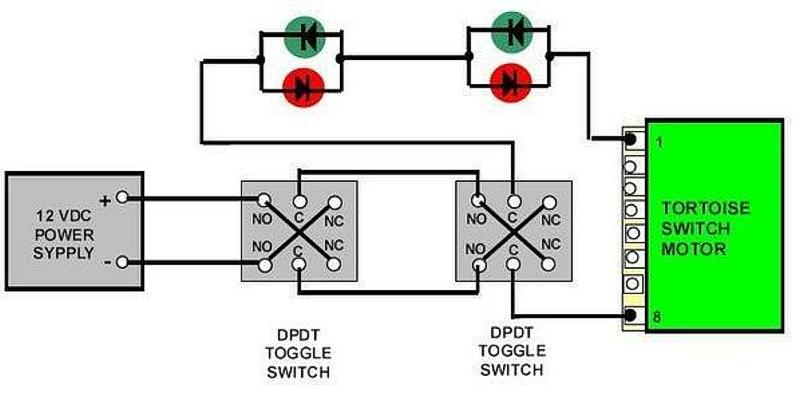
I use two DPDT switches (you can actually add as many as you like as each one, when wired as a reversing switch will reverse the polarity to the Tortoise)
I also use LEDs at each location to alert me to the turnout (point) alignment.
Unless I am missing something just wire up the second switch in parallel to the first switch. In other words, wire one and then wire the second in the same way.
The power connection can be daisy chained between the switches. Although power is always “on” to a Tortoise so maybe you cannot do that so simply. You may need a relay of some sort to kick out the one switch as you activate the other. If I understand correctly the second or remote switch just needs to reverse the polarity of the wires between the first switch and the motor, so not exactly in “parallel” . Rather like a reverse loop polarity change. An analogy might be a three way light switch pair in your house.
The switch motor doesn’t care how the power is connected to the return wire selected by the switch. Just that it is connected only one way at a time. If it isn’t possible using a Tortoise then consider using a twin solenoid switch motor for that one turnout. Those can be common wired to several switches.
Of course, if wiring in parallel would work, you still would not want to activate both switches in opposite directions simultaneously but one assumes your issue arises because your arms aren’t long enough to reach.
I use only twin solenoid motors at the moment but I have Walthers Tortoise version.
I was about to suggest inserting another DPDT switch in series upstream of any indicator lights. Whichever way is most convenient from a wiring run perspective.
I’m glad that diagram helped some of you fellows out. The LEDs are optional, of course, but with the turnout points being a distance away you certainly would want a way of knowing which route is selected.
All of my toggles for turnouts are setup so the lever is down for the “normal” route. On the ones with two or more toggle switches I have those set so the lever moves side-to-side.
I just made that quick sketch back when we were discussing this in the earlier thread. I’ll have to clean it up a bit and repost the diagram. Maybe even make a sample of the wiring for a photo.
Ed has shown the easiest way to wire multiple Tortoise control switches. No relays required. Relays would complicate the wiring enormously. At a minimum they would require another power supply to operate them. Absolutely not necessary.
I agree with Ed’s drawing. I was going to work up a CAD drawing but I found a nice diagram on another Forum.
I might point out that having LED indicators at both switches is kinda necessary, the Tortoise DPDT switch handles won’t show the position of the turnout. They will work like the two way light switches in your home, up doesn’t always mean on.
Thanks, yes, I was rambling a bit. For “always on” turnout motors the solution is quite different to wiring that would work for the twin solenoid momentary contact motor.
Because of the live polarity always being present, wiring two motor switches in parallel wouldn’t work for servo motor types.
Ironically, it was thinking through the electrical flow through a remote relay switch that allowed me to understand the simple solution: a second DPDT control switch in series with the first.
Even if the control switches were directional indicating the DPDT switches in series would also keep reversing the indicated direction if you used them alternately.
Either two sets of indicator lights are required or the one set needs to be visible from either switch location.
Using 2 switches for a Tortoise, they would be wired in series. It would be like having “3 way” light switches in your house - they wouldn’t always agree by handle position. If the indicator lights are wired in series with the Tortoise motor though, they would always indicate correctly at both locations, even if the toggle handle doesn’t agree. Pushbuttons and a latching relay, along with indicators, would allow for multiple location control with always correct indicators - Sheldon has posted a digram for this before, just using relay diagrams instead of electrical schematics. With the latching relay and pushbuttons, you aren’t limited in number of operating loccations (well, you aren’t with a series of DPDT toggles, either, but you end up with wires running all over the place, both for the switch wiring and for the indicators). If using relays bugs you, Rob Paisly has some circuits using a 555 time to switch a Tortoise via poushbuttons, and he may have one using other digital logic as well - if not, such circuits are all over the place. It’s fairly easy because of the low current draw of a Tortoise, although the 555 timer version has enough output current to handle the higher current Tortoise alternatives like Cobalt.