I’m in the middle of building an 11x15 two level HO layout - my first using DCC. My system consists of a Digitrax Super Chief, with a second booster & DT400 controller. Track power wires will be routed thru two DCC Specialties PSX4 breakers.
I have not yet mounted the system, and am really interested in seeing how others have done theirs - particularly Digitrax systems. Soooo, if you would kindly post a picture of your set-up, it would certainly be appreciated.
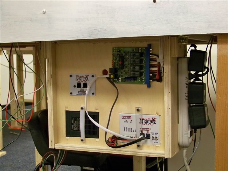
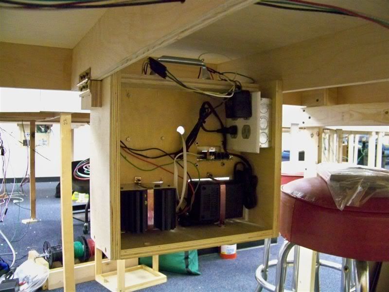
I am constructing a modular/domino HO scale layout around the walls of a 1800 sq ft basement. My DCC system is located in the center of the basement. When I had the hosue built, I had the electrical contractor install a dedicated, switched 20 amp circuit for the DCC system. The DCC power supplies plug into a computer power strip (located to the right). When I leave the basement I turn off the switch, which cuts power to the layout.
I use 12 ga solid house wire from the DCC command stations for my power buss. I also have power and programing connections to a test track on my work bench.
The layout is still in the “plywood pacific” stage, but open for simple operations.
Can’t post a photo, haven’t taken any, but my railroad is three decks, 33ft by 28ft in two basement rooms. I use NCE, the command station and the four boosters for the power divisions is located on a shelf under a switching yard. It is a center point as far as the power buss and command busses. the power unit for the track switches is also located on this shelf. But they are covered with curtains hanging from the facia and do not show normally. The radio unit is on the ceiling and connected to the command station. The curtains allow the command station lights to show through the material so I can see a short. The facia plates for the plug in throttles are spaced 8-10 ft apart around the facia perimeter.
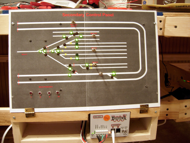
I don’t use control panels, no need for them with DCC. The facia board hold the throws for track switches at the appropriate location with a small diagram also on the facia.
I forgot to mention that I have a programming track on the shelf with the command station. I believe in keeping the electronics out of view and away from curious hands, and a simple as possible.
Thank you all for your pictures, comments & advice.
I’m in the process of designing the “system component center” and want to make it as user friendly and efficient as I can. As I am just finishing up the wiring of the lower level, I’m only working with three blocks feeding into the breakers, but will have 8 blocks when the layout is completed (wiring wise).
Funny thing, but during layout construction we often spend a lot of time “on our backs & bellys” under the layout putting together all the wiring & components that make the RR work. Yet, it is relatively rare that you see pictures or write-ups about this part of layout construction. I realize that the underneath of the layout is often pretty rough - as compared to the layout surface - but it is a most important part and yet often taken for granted.
I do hope the pictures keep coming, and I promise that when my layout is complete (wiring wise), I’ll post some too!
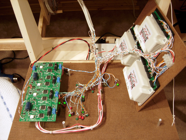
Don’t have any pics, but I used a piece of plywood, hinged, with a hook and eye. On a friend’s layout he did the same. The cables come in at the hinge end, connect to circuit breakers on the board. We also left room for a BDL168 for block detection. To work on things, you unhook the hooks and drop it down. Once completed, you lift it back up under the layout and latch the hooks. This way everythign is up underneath and out of the way, but also easily accessible for work.
Does half Digitrax count? Command station and DCC system is NCE. The EB-3 is a three section circuit breaker. Wiring is still under way so the wiring hasn’t been tied up in this photo yet.