I am currently using the RTS 8.0 (I have the 10.0 loaded but seems to have a problem) to work out a new layout. Finally start to get the hang of it! When I get closer to the plan I want to build I would like to post it for folks here to review and give me tips.
But I have yet to find away to turn the plan into a format I can post here on the site. Any tips other than printing it out then scanning it as a picture file?
Ken, I had loaded and installed version 10.0, and it did have a problem when you tagged track. Basically, when you removed a piece of track, then tagged the track that was connected to it, it would tag ALL of the track. They seem to have since fixed that problem.
To save the layout in another format, click on “Save As”, then, you can save it in bitmap (.bmp) format. Once that’s done, I use Picasa or Windows Live Photo Gallery and save it in jpeg format. Then you can upload it to an online photo site (I use Photobucket).
First, click the “save as” button. not the save, but the save as.
When the dialog box open, go to the second bar that says “file type” or soemthing like that
select either bitmap (.bmp) or JPEG (.jpg)
click the save button
you don’t even have to change the file name if I remember right. however, every time you change the rts file, you’ll need to the same for the bmp or jpg file version
here’s one of my rts 8.0 plans (I dressed it up in Microsoft Paint)
I do all my track planning in WinRail, which is the Atlas source of RTS. I am using version 8.0, which lacks the 3-D feature, but I don´t miss it.
With a little exercise, you can draw good looking track plans. I mostly use the “draw” function to enhance my plans. By now, I have quite an intensive library of structures, which I can copy and paste into a new track plan.
My recent plan:
My most elaborate plan:
The locos and cars, as well as all structures are drawn in WinRail (RTS)
I’m not familiar with WinRail. It sounds interesting but before I download anything to my computer I like to have a really good idea about what it is. From what I have been able to find out it can be downloaded free but there are other indications that it is a program that must be registered implying that there is a free anotated version and a full registered version. Which do you have and can you give us a little more information since you seem pleased with it?
RTS and WinRail are the same product, the key difference being that RTS is limited to Atlas track, whereas WinRail has a much larger library. And, yes, I had to purchase WinRail. Other than that, there is no difference, all the functions WinRail has are also available in RTS.
As with all CAD track planning programs, there is a learning curve to RTS. It took me some time to find out, how to shape flex track. There are some other quirks, but I still find it easy to use. However, as with all CAD programs, it will not take away the design effort - it just helps to verify that your idea is fitting into the space you have dedicated to it.
I don´t know whether you have to register to download RTS from the Atlas homepage. In any case, it is a freeware with all functions available.
I too have run into the ‘tagging’ issue on RTS 10.0. I sent a note to RTS@atlasrr.com as of last Thursday, but have not gotten a response from Atlas yet. I did remove RTS 10.0 and downloaded a fresh copy - same issue. A look at the help text indicates that I still have the same level/date of RTS 10.0 after upgrading again. Anyone know how to get this ‘fix’ mentioned in the above post?
Ken, I don’t really see much difference between versions 8.0 and 10.0, but then, my layout is pretty much complete. I just downloaded 10.0, because I wanted the newest version. I was hoping that they would have included track libraries for other manufacturers other than Atlas. Nope, same ones… lol
Jim, I just tested the tagging issue and found that if you use the “cut tool” (the little pair of scissors), then you can tag the other track. But, if you just use the “disconnect” tool, the tagging problem still remains. I’ll be going back to version 8.0.
Dan do you think a 20 foot reach is to much? [:D] Yes the center will be open and maybe a duck under in to top right corner. At this point I am just trying to get a feel of what I can do in the spaces I have.
Ulrich as you may have picked up my now I am a rail fan and there will not be that many turnouts. The section that has the bloop will all so be 3 to 6 inches higher than the other line. More than likely after I have the basic plan down I may add turnouts on the plan. Or I may just wing it on the fly as I build.
My goal’s are 4 to 6 main lines with some elevation and no smaller than a 26 inch turn unless it is in a yard or spur.
It is amazing how fast HO scale eats up a 19 X 20 foot room.
Yup, that would not be a surprise on a CudaKen plan. What I find interesting is how close it looks to a start up plan I drew for grandpa coyote about 6 years ago. That was a twice around, but sure looks similar.
Sure looks good to me too. Now that you have that, you also have the option of turning off the gridlines, drawing your benchwork with the line tool (click when you want a corner, right click when done) then you can save as a bitmap and open her in paint to do fill colors.
Tips for flex track: To get larger radius turns, build yourself a crossover from two switches. Then even out one end so that the ends of the straight path of one switch and the portion before the frong on the other is flush. Copy this, and paste it. Then, link the two together with a 22" radius curve on the inside curve. Then use the flex track tool to link the outside track, straighten the lengths witht eh Flex editor sliders, and press Optimize. That should be 24". then unhook the switches, move them over so the 24" is nowe the insdie of the curve, and do it again. That’s 26", then do it for 28", 30", until you have the radiuus you want.
If yo know you want a 36" radius for a 90, 180, 270* turn, place a 9" straight on the grid with one end lines up squard in a corner (easier to do with the track set to a line), then place a second one, flip it 90*, and place one end on the grid below it three junctions over and down. (Rise and Run from Geometry & Algebra). then lay flex track from point to point and optimize it. 4x4 gives you a 48", an2 2x2 is 24".
Amazing what you can find by just casually surfing through articles on the forums.
Having used both RTS 8 and 10 (and going back 8.0 for now) to design my layout (now being built) I picked up a few tips from veterans in here to help my layout construction in RTS.
The Tips of the flex track above were extremely useful - knowing that I use flex track a lot in all sorts of places.
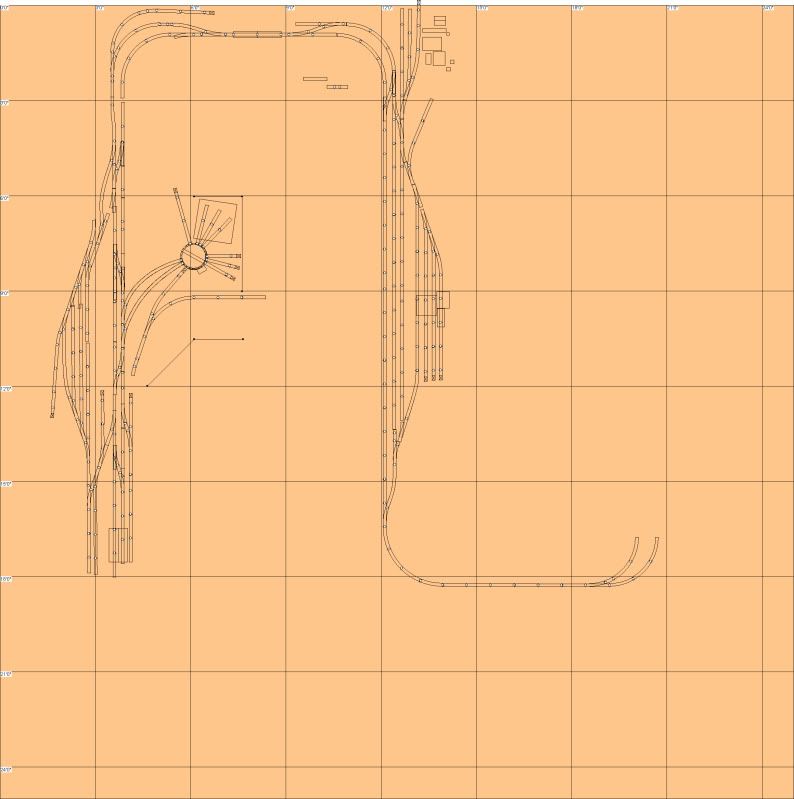
I’ll leave a copy of the RTS layout I had under way - and that still changes on a near daily basis when building the actual layout in the garage (especially now that summer is coming)
More on my layout can be found at my blog (link in my profile)