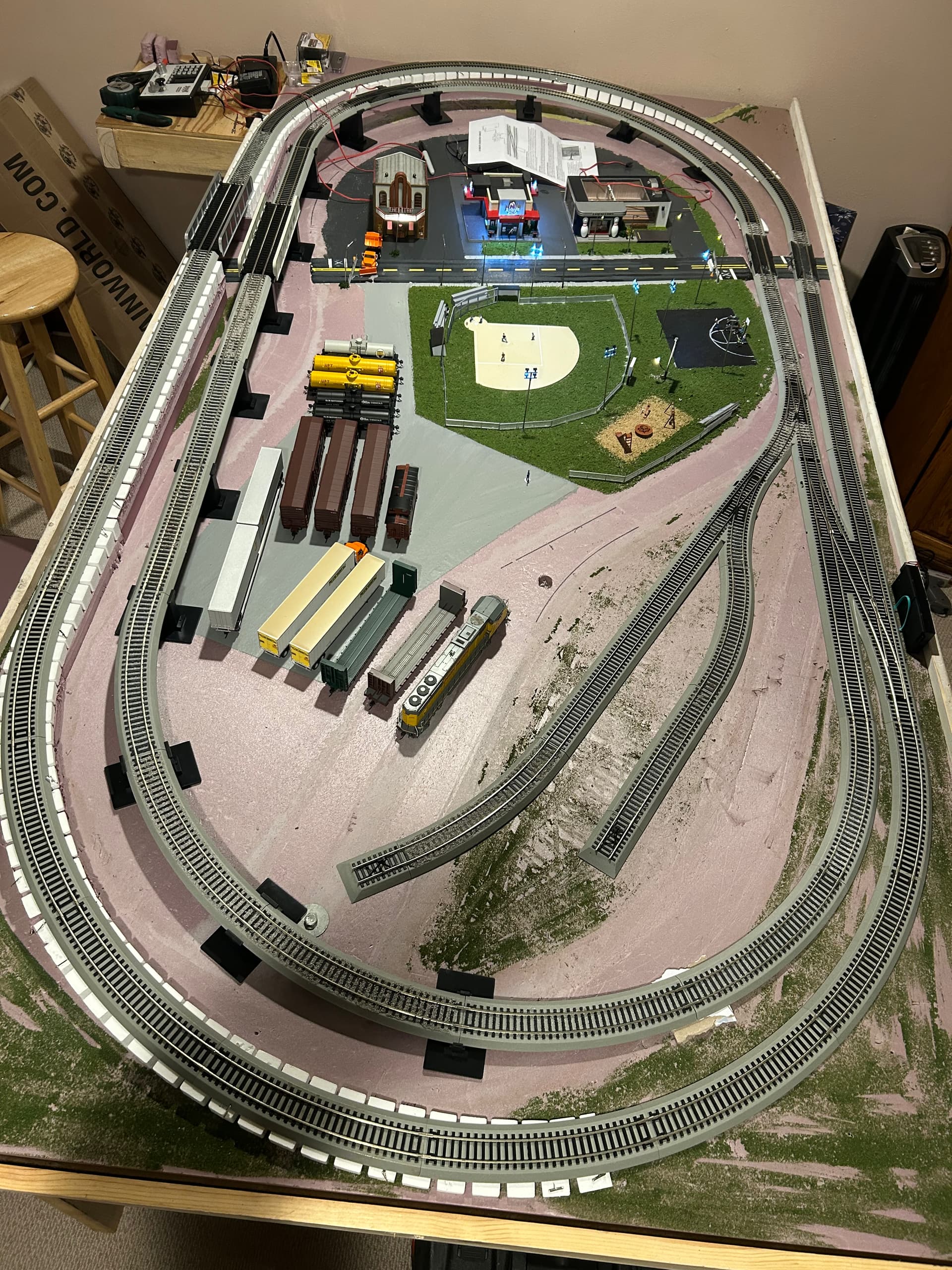
Bachmann EZ Track Nickel track and getting a Local Booster Track Fault as soon as I install the #6 Remote Crossover Turnout on my Zephry Express 3.0 Digitrax regardless if I have 1 or multiple terminal feeders plug in. I kept my inner and outer loop consistent but still getting the fault (Rail A on right side for both loops). If I disconnect the turnout then I don’t get the fault even with an incomplete circle but once I connect the turnout even with an incomplete circle I will get the fault. FYI, the frogs have been disconnected. Is my turnout just faulty or am I missing the obvious? I’ve read other forums but seems like the fix was the rails weren’t consistent (Rail A not on same side for both loops). Thoughts?
Not familiar with that style of track, but my suggestion would be with your power pack unhooked. Take some readings with an ohm meter with the turnout connected and disconnected. This may reveal whats going on.
1 Like
I can’t help you with your issue. However, the Bachmann forum has a discussion on the topic.
See https://www.bachmanntrains.com/home-usa/board/index.php?action=search2.
I think you have to join that forum to see complete answers. Probably free.
Search for crossover shorts.
1 Like
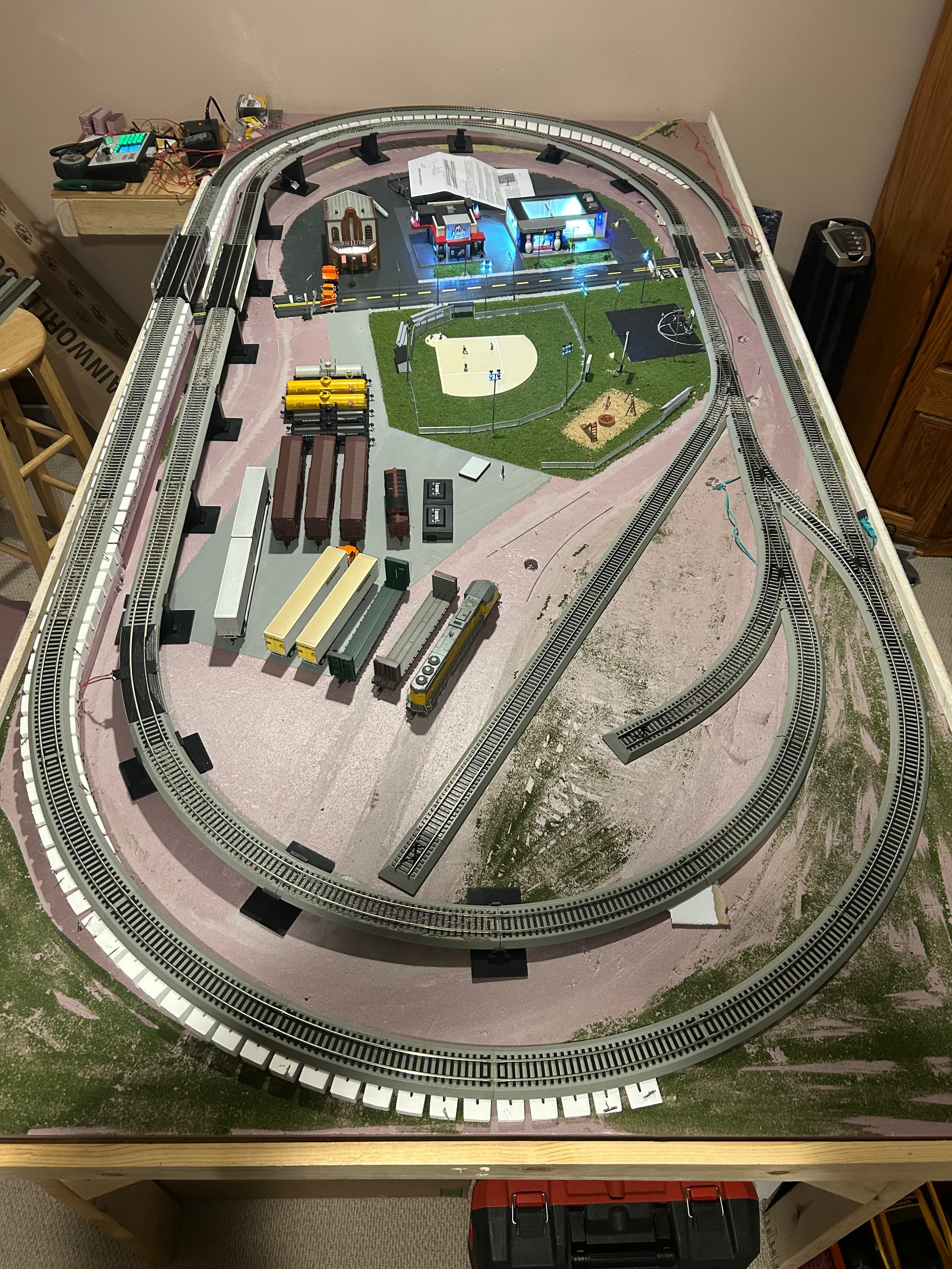
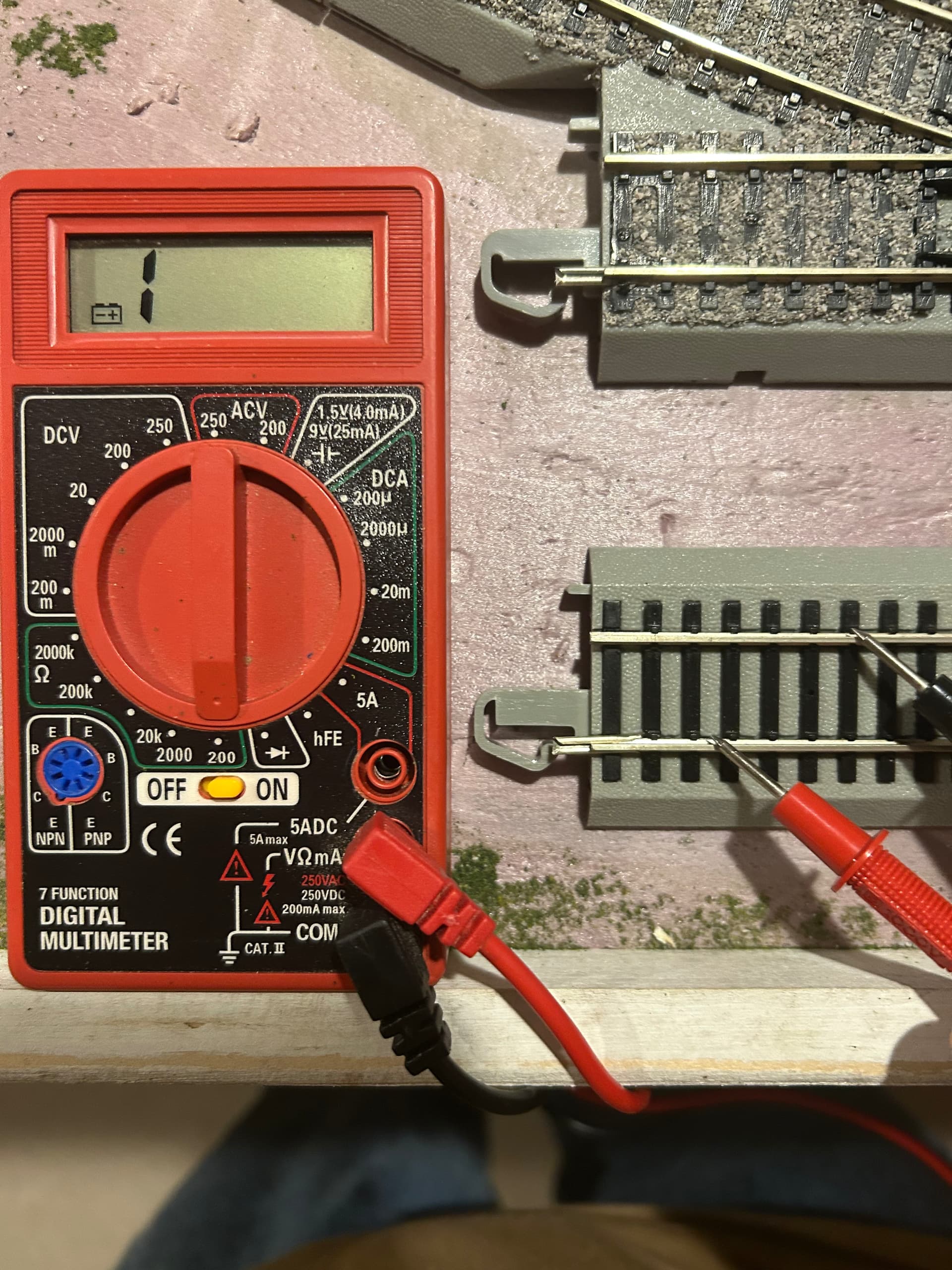
My readings are roughly 3 watts around the track between the track fault beeps but once I check the crossover turnout it reads either a 0 or 1. When I disconnect the opposite ends of the crossover, the readings are the same. When I fully remove the crossover turnout and install multiple turnouts then I don’t receive the fault and throughout the track receives 3-4 watts (see new picture). When running a locomotive then I receive higher watts. The reason I wanted to install the crossover turnout was because my running stock would constantly derail on the turnouts. Not sure why since it would happen on different turnouts and different stock each time. Thx for the idea of looking into the wattage though.
Did you mean volts or ohms?
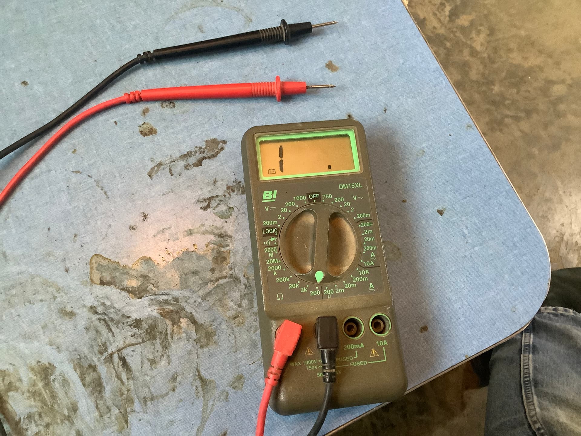
Ope, my bad. I wasn’t using the digital multimeter on the correct setting. When checking the ohms, the crossover turnout reads 0 when attached or unattached to the loop. The loop reads 53 until the crossover is attached. Once attached, it reads 0. I tried attaching the crossover to one end while the other three ends unattached and again the reading is 0.
Hmmm that 53 reading seems unusual though i would assume different multi meters may report things in a slightly different manner. Particularly the non conductance reading.
Mine reports that as a 1 off to the far left of my display. From my experience i take these readings with my meter set to the lowest scale possible. As i have found for simple conductivity checking some times i get erroneous readings probably because of a poor connection when i try on a higher scale.
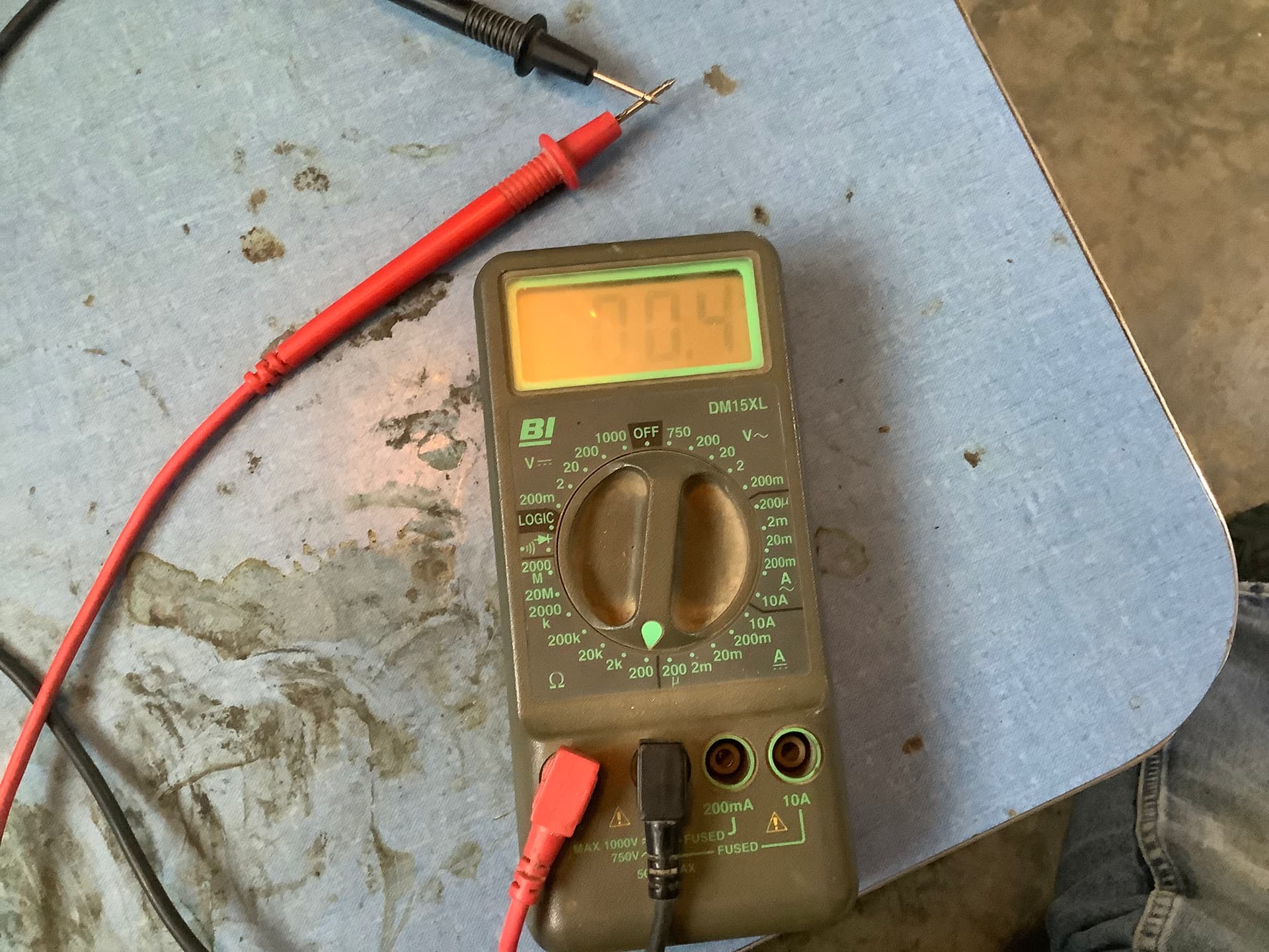
There is a bit of a glare but the second picture reading is 00.4 on the lowest setting of my meter. Perhaps the 53 was just a poor connection to the track showing a bit of resistance. (Assuming there were no locomotives on the layout while you tested.) Maybe try again if the first set of readings were taken at a higher scale.
As i was saying i am not family with the Bachman stuff. Or your particular multi meter and how it reports a non conductive state. But if all your readings are 0 in each loop and the crossover when disconnected they should be the same connected.
Is it possible the problem is in the power supply?
Sometimes having some weights in the cars helps with the derailments.
I’m not sure what the 53 means. You should be reading infinite.
The “0” means that there is a short. If you’re seeing “0” on the crossover, connected or not connected to the remaining track, the means to me that there is a x-over issue.
Is this a manually or electrically operated x-over? If electrically operated, I would make sure that none of the wires are touching anything. If nothing is touching, I’d be of the opinion that the x-over is the problem.
Oh, I’m assuming that you are reading from track A to B.
Good idea on the weights. I will have to experiment with that when I figure out my layout. I changed my meter to the minimum ohms setting and received a 1 on the loop when not connected to the crossover.
The crossover readings fluctuated but was above a 1.
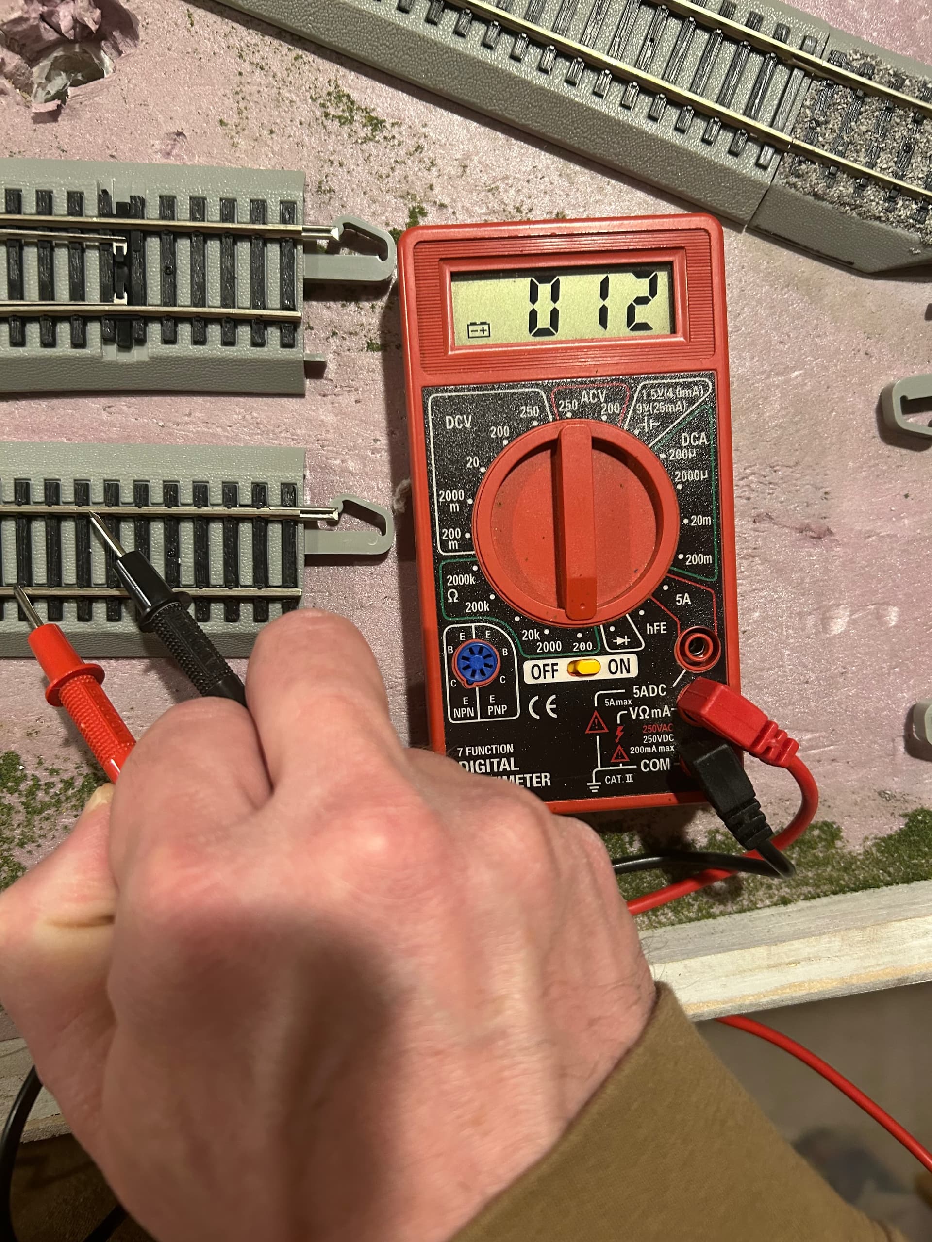
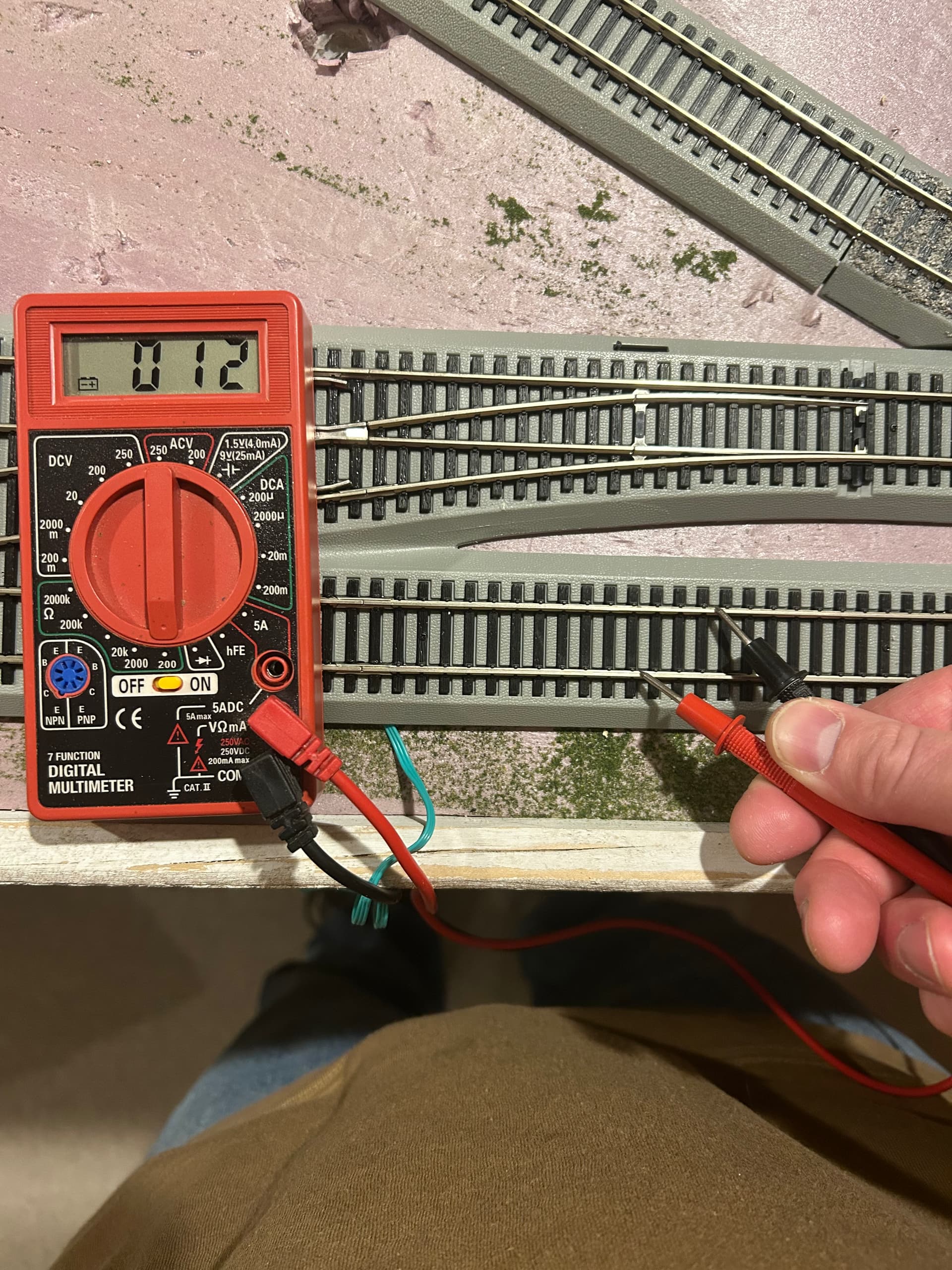
Once connected, then my loop changed to greater than 1. See pictures in case I am not checking my readings correctly.
I am new to the hobby so I have lots to learn. Thank you for giving me things to look at. Not sure if Bachmann customer service is helpful but I plan to reach out to them when I have time. I read quite a few forums on Bachmann but still unable to crack this issue.
You can"t read greater than one.
That’s not one. That 012 is almost zero, which indicates a short. I still say the crossover has some sort of issue.
By the way, did you purchase the x-over new, or was it pre-owned? If new was it from a hobby shop? Take it back with your meter and show them what’s happening. If new. you can also call Bachmann and explain that when you check across the rails with your meter you are seeing almost no resistance.
1 Like
If you remove the crossover and put in regular track, to make two separate ovals, does everything work then? If not, it might be one feeder connection isn’t right. If it does work, then it’s the crossover.
Can’t tell from your picture, are the tracks in the middle of the crossover electrically gapped?
1 Like
Yes the 1 displayed on the far left is the infinity of no connection.
I would also have to agree that the problem is in the turnout (either manufacturing or as pointed out by @wjstix
It could be a case of incorrectly wired feeders.
Pretty sure it isn’t a crossed feeder issue.
If the two rails connecting the two turnouts aren’t gapped - and I have read that has been a problem with some Bachmann crossovers - that could be the problem. May need to cut gaps in each rail.
Hey, Jeffrey, did you get this resolved???
No. I contacted TrainWorld and they weren’t sure. The crossover turnout might be faulty but they directed me to Bachmann for additional assistance. Bachmann has not responded. ![]()
Me neither, I think it’s a gapping (or lack of gapping) problem. That’s why I wanted to know if the OP’s layout worked OK if he replaced the crossover with regular tracks. I suspect the problem is the turnout is power routing, and is causing a short when it’s thrown to cross from one line to the other because the rails aren’t properly gapped between the two lines.
1 Like
Each loop works independently when the crossover is disconnected or you use 2 turnouts instead of the crossover.
When the crossover is disconnected from the loops it shows a reading of 0.12 meaning there is a fault as it too should read 1 just as your loops are.
I agree there is a gaping issue in the crossover
I hope you called Bachman and are not waiting for a reply to an email.
UPDATE: I got a hold of Bachmann and they believe the crossover turnout is faulty so I will be getting it replaced. Hoping for the successful outcome on the replacement!!! Thx everyone for your ideas. I have gained more knowledge during this issue.
1 Like