Looking for some suggestions. I have seen photos of some of the really impressive bridges you all have built, and want to give it a try!
I work in N scale and looking to build a truss bridge somewhere in neighborhood of 350-400 scale feet. One issue is that because of space restrictions it has to be built on a grade (approx 2 pct). Any suggestions, advice, issues, etc.
Central Valley offers N scale truss bridges, and Micro Engineering has various bridge-building materials, but these suggestions would work only for a multi-span bridge.
A single-span truss of that length would be higher than the 150’ one offered by CV, and the individual members would likely be heavier than those of such a shorter bridge…perhaps a kitbash of the HO scale version?
I think the idea of 2 Central Valley 150’ spans, with concrete piers, as the main span, and then fill in on each end, or either end, depending on what the bridge is spanning, with the Micro Engineering parts for the approaches.
I like those pre-made wood bents. I didn’t know those were availiable. I think they would be more suited for a trestle type span.
When installing, be careful to prevent any track bumps, vertical kinks and twists at transition point such as the transition from adjacent land to the bridge track. It takes paying attention to how level two rails are on the approach, getting the first piers exactly the right height, not stacking joints (plywood, roadbed, rails), etc. No problem having on a grade as long as done carefully. I had a bump and some twist on one end of my HO truss / girder combo. It didn’t cause derailment but the train cars showed off the problem. I had to do some troublesome adjusting.
Paul, back in the day Frank Ellison actually modeled a little bobble into each end of a bridge. He claimed that the roadbed had settled, but the abutments hadn’t.
Back to the 450 foot truss on a 2% grade. Just what requires 450 feet of clear span? Are you leaping across a canyon, or bridging a channel used by oceangoing ships? Or is the ground in the flood plain semiliquid mud several hundred feet deep?
The reason I ask involves civil engineering economics. A railroad wouldn’t use a long, expensive bridge (which, in the case of a through truss, would also raise clearance issues) where shorter, less costly bridges could be put on intermediate piers set on stable ground.
If the situation really requires a long, tall truss it would probably be a site-specific design, The vertical members would be vertical, while the floor and ‘horizontal’ members would be designed for the actual track grade. The bridge panels would be rhomboids, not rectangles.
Fun, isn’t it. That’s why I personally prefer deck girder spans. (Painted oxide red. It’s a Japanese thing.)
Chuck (Modeling Central Japan in September, 1964 - many bridges, no long trusses)
Speaking of bridges, I would like to share a recent mistake I made building bridges on my HO layout that might help someone in the future. I needed to cover a 600’ section of double track mainline with bridges going over a swamp. I wanted to use a combination of Central Valleys 150’ double track truss bridge with their 72’ double track plate girder bridges. But the problem I ran into is the truss bridge has a 2" track center line and the plate girder bridges have a 2.25" track center line. So now i’m thinking of a different plan of maybe using a pair of ME’s open deck plate girder bridges in which i can make any track center line I want.
This is one of the Central Valley truss bridges that’s been mentioned. Mine is in HO scale.
I’m going to add a word of warning on this kit. It’s not for beginners. The box girders you see must be assembled from flat parts and then cut to size, and the ends must be beveled. They must be matched to a template to get the size right, and then glued together. I found it to be an enjoyable challenge, but it certainly was a challenge at times.
I am going to try to model the SP double track main over the American River out of Sacramento to Roseville. It has 5 spans supported by concrete piers.
Wow ! that will be quite a project. I just checked it out on Google Earth. I read in Mr.B’s post about assembling a Central Valley kit, which sounds like a challange by itself, but you will have multiple spans, on a skew, which will add to the challange. Thats going to be a fun build!
Yes, the Google Earth images are impressive! I am thinking of using either the Cornerstone kit or Kato readymade truss bridges for the three long spans, but will have to scratchbuild/kitbash the two shorter spans.
I have never tackled a project like this. It might be easier to use a kit so I can use my Peco flex track? reduce opportunity for “kinks”?
My thought is to build it all on the bench then install on layout?
Unless anyone has other thoughts?
At any rate, I better do something or my railroad will never get to Truckee!
I recently bought two MTH bridge kits. Thes are super easy to put together and can be kit bashed too. I have four on my layout. I’ll try to get some pictures.
If you have been in model railroading for a while, you might believe ( like me ) that these are the old Atlas arch bridges. The bridges that Atlas makes now, IMHO, suck.
I have also assembled two Central Valley truss bridges. They were a real pain as I am not set up or equiped to cut the parts to size and do it on an angle.
If your prototypes are skewed bridges, I think that the Central Valley bridge would be a better choice, as there’s more room in the construction method for making alterations. That includes both skewing the spans and shortening them.
If you’re going to the time and expense of creating realistic models of the prototype, use bridge track. It comes with the CV kits, but you can also use the bridge track from Micro Engineering or Walthers/Shinohara.
As long as your measurements are accurate, it’s probably easier to build the bridge and the supports at the workbench. Depending on the type of supports, you may be able to modify them, if necessary, during installation.
This is my version of the Central Valley bridge:
There’s an Atlas through girder bridge, re-built as a deck girder, on either end of the CV span…
…and a Micro Engineering 50’ and 30’ deck girder beyond those:
Thanks for the detailed response. Good tip on the ME bridge flex track. Another thought struck me when reviewing your suggestions. My original thought was to use flex track through the ends of the bridge for some distance, but I assume you would recommend ending the bridge flex right at the end of bridge? This would make it easier to perform maintenance/repairs later on on the bench?
In the second photo, you can see that the bridge track extends onto the roadbed at the ends of the bridge. The rail joiners there aren’t soldered (although they could be), so it’s a simple matter to push them back onto the flex track to remove the bridge. I thought that this would be easier than having the joints on the bridge, and it also allows the centre guardrails to extend beyond the bridge, as is the case on many real bridges.
I still haven’t got around to adding some loose ballast at those points, though. [:$]
This is one end of my Central Valley bridge, before ballast and my Envirotex water:
The black ties on the bridge itself are part of the kit. The instructions say to bend all of the individual “spikes” that are molded on to hold the rail in place. I found that kind of awkward. Instead, I used CA (cyanoacrylate, or “super glue”) to hold the rail in place on the bridge ties. The bridge is on a liftoff section just under 3 feet long, so I removed the ties from the center of a piece of Atlas flex track so that I have a continous piece of rail from end to end on the liftoff, spanning the entire bridge and both approaches.
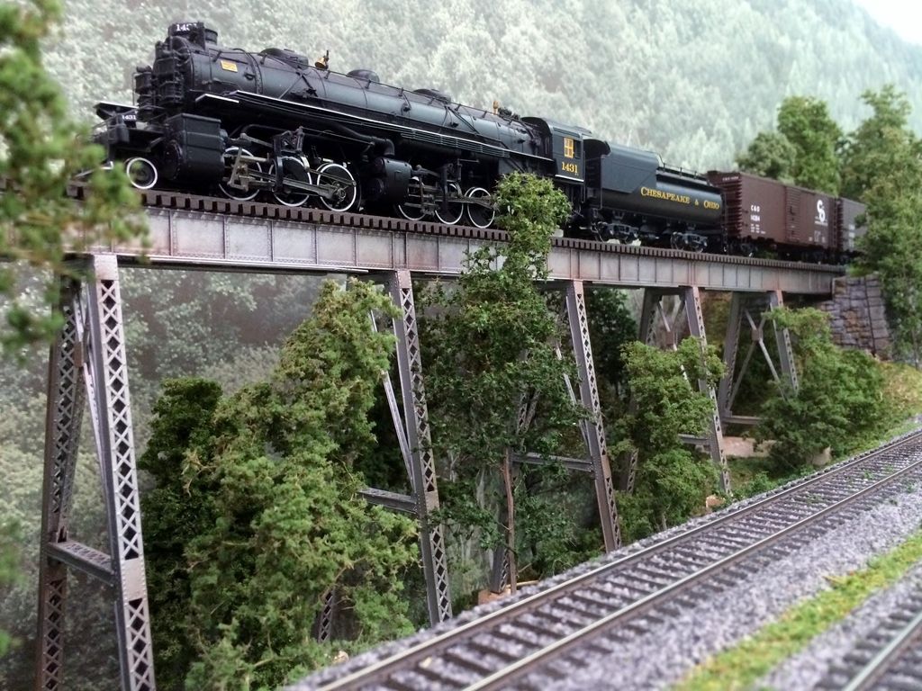
On this Central Valley model, the girder structure beneath the track bears all the weight. The beautiful truss structure above is just for show and adds no structural strength. Here, in a construction photo, Gigi pulls her train across the girder while the truss was still just a pile of parts and Squirrel Creek was just a bunch of pink foam.
Thanks for giving us a chance to talk about and show our bridges. Trains are at their best when crossing a bridge, and you are doing the right thing by modeling one.
I took a look at those MTH kits and at my old Atlas Chord Bridge, and they are very similar if not exactly the same. The MTH ones have bridge shoes and come with piers, while the Atlas bridge did not have those, but the superstructures look the same. This is my version of the Atlas Chord Bridge, which is out of production:
It is a very easy kit to assemble and paint. I think the Central Valley bridge is a far nicer and more detailed model, but this is a good bridge, too.
Ahh, bridges… one of my favorite topics. No problem building on a grade, but as always you need to watch to make sure that there are no dips or bumps at the transition onto the bridge.
I can’t speak to available kits for N scale, but to me the trickiest part is to get abutments/piers to match the style of bridge, look natural and fit right so that the track heights meet exactly. So I’ll concentrate on my experience with that aspect.
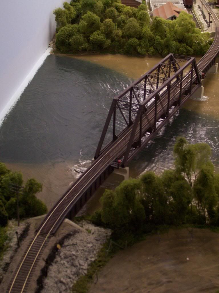
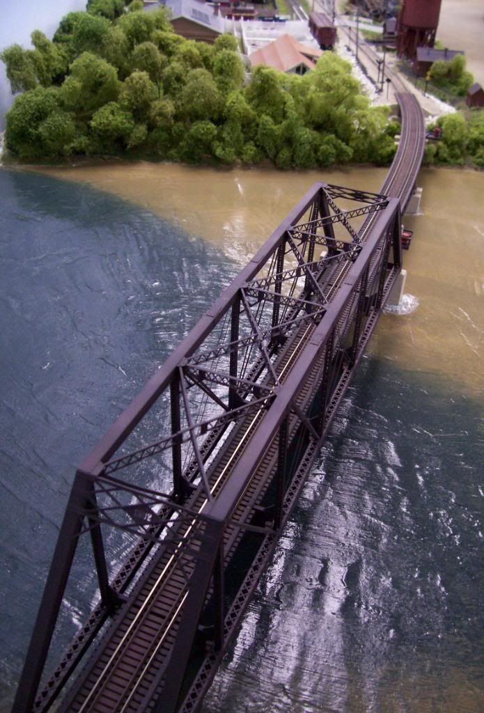
Here are the first bridges I built, in service without any problems for several years. The wood trestle is stick built with hand-laid rails. It is on a grade and a curve. I built the main structure on top of the ply subroadbed, then cut the section of subroadbed out, formed the terrain, added the bents and fit the bridge in place. There are no real “abutments” other than lumber supports that fit into the rockfaces at the ends. The two small bridges are 'bashed ME kits with ME bridge track. The abutments are plaster poured in place into wooden molds that I built and fitted into position. Wooden retaining walls hold back the ballast. Totally different looks but all are meant to be “old-style” bridges that were hastily constructed.
I built this viaduct from an ME kit and Walthers bridge track. For this one I used cast plaster walls for the abutments and also castings for the footings. The abutments are built with an inset for the bridge ends to fit into. Lots of undergrowth under/around this one so the abutments are not very visible.
I kind of cheated on this one- after searching for a good while for a double-track truss bridge kit I found this brass bridge.