Season’s Greetings and Good Evening, Crew! I think that I have the signals needed for my layout. First, take a look at my trackplan. At either end of the yard throat are locations for signal bridges.
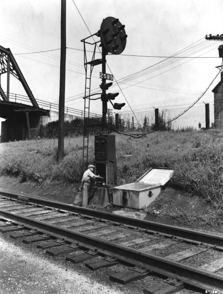
While trying to find the appropriate signals, I came accross this photo from Trains Mag that shows a relatively short distance between the signal and the crossover. This would fit well with the distance between the end of the tracks on the layout and each crossover.
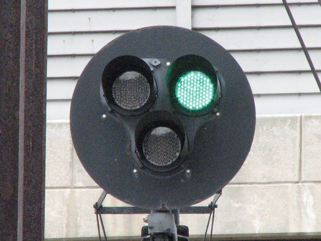
Now, while looking at the Erie’s 1952 (my modeling era) color signal aspects, I found two seperate signals that I want to use. The first is the three-color “Proceed Through Crossover” signal:
But, to me, this signal would also need to include an absolute stop when there are switching operations taking place. The Erie absolute stop signals can be seen here:
My question is how can I incorporate the “Proceed Through Crossover” signal with the “Absolute Stop” signal on a signal bridge? Thanks, Guys!
Thanks, Mark. Would that mean the lower signal would function as a multi-color searchlight showing either red or green? That would allow both rule’s signal aspects to be used on a three-light vertcal signal head.
Where on your layout were you planning to place this signal? I’ve seen different photos of ERE signals and it showed that some had two round signals mounted high on a interlocking and other interlockings had a pole with two round signals facing the direction of the camera or looking the oposite way.
I’m not sure how ERE set up it’s signals as I don’t model that road, but on any railroad here in the US, a signal or set of signals would be seen every few miles or so.
Does anyone know what those round shaped single bulb signals are called? N&W used some as well.
Just remember that all red isn’t an “absolute stop” its a “stop” signal. The word “absolute” isn’t anywhere in the rule.
Also several of the heads will have to display multiple colors. The top would display r-y-g (plus the middle head depending on the other indications).
If also depends on the speed of the crossovers. If the top and bottom are red and the middle signal is green, then that is proceed through the interlocking at medium speed. The switches look sharp so slow speed is probably appropriate.
Thanks, Guys! I think the “proceed through crossover at slow speed” and the “stop” signal would have to be combined.
The green on the lower signal for the “proceed through crossover”, here:
And the red on the lower “stop”, here:
would mean the lower signal would be multi-colored so that a three-light signal could be used. That would make the aspects red-red-green or red-red-red. Does that sound right? The placement of the signal would be facing trains entering the crossover area. It may not be what the Erie actually used, but I’ll have to do some re-engineering here.
You need to make a list of all the signals that could be displayed at the interlocking, that will tell you what colors you need on each signal head. For example if none of the switches are lined, all main track signals normal and a straight away route is lined, then the signal would display clear g-r-r. If the block after the next signal is occupied then you might get an approach y-r-r. If you wanted a medium speed anyplace, for a 30 mph route, you would need a r-g-y. If it was a higher speed main, it might have an advance approach of some combination of red with two yellows (can’t find my Erie rule book).
Since its an interlocking you should also have a signal governing the entrance into the main track in the interlocking.
Here’s an interesting rule for you to consider. Any time a train enters an interlocking and partially occupies it, they cannot reverse directions without permission from the operator. If they completely clear the interlocking, they can re-enter on signal indication, if they completely occupy the route through the interlocking, they can reverse direction. If they nose into the limits or the rear end of the cut is hanging into the limits, every time they change directions, they have to call the operator and get permission to move in the new direction.
When the switcher pulls into the textile company the switcher needs permission from the opertor to enter the main track from the engine facility.
Will need permission from the operator to reverse directions.
Goes into the textile plant.
Will need permission to re-enter the main track when it pulls a track.
Erie1951
would mean the lower signal would be multi-colored so that a three-light signal could be used. That would make the aspects red-red-green or red-red-red. Does that sound right? The placement of the signal would be facing trains entering the crossover area.
You need to make a list of all the signals that could be displayed at the interlocking, that will tell you what colors you need on each signal head. For example if none of the switches are lined, all main track signals normal and a straight away route is lined, then the signal would display clear g-r-r. If the block after the next signal is occupied then you might get an approach y-r-r. If you wanted a medium speed anyplace, for a 30 mph route, you would need a r-g-y. If it was a higher speed main, it might have an advance approach of some combination of red with two yellows (can’t find my Erie rule book). Since its an interlocking you should also have a signal governing the entrance into the main track in the interlocking.
Here’s an interesting rule for you to consider. Any time a train enters an interlocking and partially occupies it, they cannot reverse directions without permission from the operator. If they completely clear the interlocking, they can re-enter on signal indication, if they completely occupy the route through the interlocking, they can reverse direction. If they nose into the limits or the rear end of the cut is hanging into the limits, every time they change directions, they have to call the operator and get permission to move in the new direction.
When the switcher pulls into the textile company the switcher needs permission from the opertor to enter the main track from the engine facility. Will need permission from the operator to reverse directions. Goes into the textile plant. Will need permission to re-en
One question I have is why you want an interlocking at all and why you need signals at all.
The signals are for trains ENTERING the interlocking. You appear to have less than one engine length of room on the left end and maybe an engine length of room on the right end of the layout. Basically the majority of engines operating on the layout will never get a signal indication at the signal bridges, because 99% of all the moves will be within the limits of the interlocking or exiting the interlocking limits.
The only time you would get a “slow” indication is when a move is lined through a crossover, there are no cars or engines on any main track and ALL the other main track switches are lined for the main track. There were any cars on the main track the signals would display stop, if there were any other main track switches opened the best the signal would display was low or restricting (assuming none of the crossovers are lined and the there are no cars or engines on the main tracks inside the limts of the interlocking, the speed depending on your rule book). The difference is that slow is proceed at 15-20 mph (depending on your rule book) and low/restricting is proceed proceed prepared to stop, not exceeding 15-20 (depending on your rule book.). Restricted speed tells you there could be stuff in the track you are lined toward, slow says the track is clear but go slow. Since all the other main track switches lead into yard, mechanical or industry tracks, they wouldn’t be bonded and the signal system wouldn’t know if they were occupied or not.
If your layout as drawn is a portion of a larger layout or a module that will become part of a larger layout then the signals would have more utility.
If that is your entire layout then the only place you really need signals that change color is on the right end of the layout, because that’s the only place that you could put an engine outside the limits
Dave, you’re right about the length between the end of my layout tracks and the signals. What you see in my track plan is the entire layout, but I wanted to have signals in place where they should/might be for the interlocking control of the crossovers only. Of course, this wouldn’t be a completely prototypical signal set up and I can’t model it that way, but I just like the idea and the way it would compliment the layout.
The more generic name for those is “position light” signals, they use the pattern of bulbs to mimic a semaphore arm. PRR was the main users, but N&W used them as well (PRR influence). B&O used a similar type but with colored lights.
Those lower heads with just part of the aspect as needed, still exist all along the Northeast Corridor. Same reason for using 2 lights instead of 3 when the upper head(s) are 3 light types. No point in having a capability that will never be used - which is just more that needs to be maintained evev if it isn;t used.
This is what I’ve come up with as signaling on the shelf layout that I’m building. The location of the signals obviously won’t govern moving trains, but will add a certain prototypical look to the operation. The purpose of the interlocking tower is to control the crossovers and the signals while switching operations are taking place, the main activity on the layout. Here’s another view of my track plan showing the location of the signals and their purpose.
Only the signals that can be seen from the operator’s seat will have lights while those that can’t be seen will have dummy heads. I understand that distances between signals are compressed on model railroads and this is another example, I think. Are the signal positions and purposes plausible? Thanks, Guys!
The signal positions look perfect to me. Seems to me that signals for interlockings tend to be placed pretty close to the switches they’re protecting.
If you want to add just a little more pizzazz, you might also put dwarf signals for the tracks “to west yard” and “to east yard”. Maybe even for the diesel house tracks.
I love dwarfs, and am disappointed that none of the track plans I may build would call for any.
GENERALLY, the signals surrounding interlockings face outwards only. Your sample photo at beginning shows such an exception, but I don’t believe it’s common at all. By that reasoning, you have to have a good reason to have a signal facing inwards. And note that that signal probably would not be controlled by the interlocking tower.
Of interest to me is that there are “city interlockings” and “country interlockings”. The sample photo shows a country. The layout is a city.
A country interlocking tends to be high speed. The UP has a lot of double track on its mainline. And there are high speed crossover interlockings scattered along it, out in the middle of nowhere. Crossover speeds are usually 45 MPH. Through tracks are track speed, I
Thanks, Ed! The reason why I show dummy signal heads on the opposite side of each signal bridge is to control trains coming through the yard area in both directions, not that any will really be doing so on this layout. LOL. I like the idea of using dwarf signals to control yard switching movement, the layout’s main activity, but it appears the Erie only used them in terminal applications. The crossovers will act as a run-around for switchers working in-bound freights to be broken up with empty cars moved to storage, and out-bound short freights put together for further transfer to the DL&W. The tracks between the signals will give me 3’ to 4’ to work with between the crossovers for the operations. That photo that I posted of the crossover and signals was just meant as an example of the proximity of a crossover to the signal, something that I needed to use as a guide for my own layout’s signal placement. As always, I appreciate your comments.
The “layout’s main activity” may be switching to you, but to the real (HO) railroaders who are running it, it is an interlocking, with peripheral stuff. I say that because you want the layout to have a real-ish look to it, even as you run it as a primarily switching layout.
I am only a model railroader. I haven’t worked with signals professionally, as I believe Dave has. He may well correct me on the following:
An interlocking is a little piece of geography–a strictly bounded piece of land. Inside this piece of land are an assortment of track switches and maybe crossings. Entering this piece of land are various tracks from “outside”. There is a signal at each entry, facing outwards, to tell an engineer what to do. Once allowed into an interlocking, the job of the engineer is to get out of the interlocking (no stopping for a chat). The in
To that point there are only TWO moves that can be made where the signals will not be all red and the only signals that can display those indications you have indicated are dummies. You could realistically set ALL the signals facing the interlocking to all red and all the signals facing out to high green and be 95% prototypical (if an engine or car passes either signal bridge teh outbound signal would drop to red. There is no move that I can see your switchers making that would get a r-r-y signal.
The only time a train would get a r-r-y signal is if it was outside the interlocking limits, the crossovers were lined for that train’s movement, ther were no other switches lined and no other piece of main track occupied by a car or engine.
The leaving signals in most cases would be part of the block signal system, so would be automatic. The interlocking operator woud not control them. They would dispaly the best signal the track conditions will permit. One signal they would probably not dispaly is r-r-y because that tells a train to go slow through crossovers in an interlocking. On a leaving signal, its LEAVING the interlocking so that signal doesn’t make any sense operationally. The crossovers are behind the signal.
There are only TWO types of track on the layout, main track and other than main track.
You have to decide if the main track switches are hand operated by the crews, or controled by the tower operator. If they are tower operated, that adds a whole additonal level of complexity. Every time a switch has to be lined the crew has to communicate with the tower operator, the train has to clear the interlocking (no train, engine or car can be on the main track
I’m not familiar with interlocking signals that include an inward facing component. Could you please show some examples?
I do see that the b&w photo already posted has two. But not four. Why would that be?
You mention “The leaving signals in most cases would be part of the block signal system, so would be automatic.” Thus ABS, or something similar. In that case, wouldn’t there be inward facing signals on most or all tracks that had outward (interlocking) signals?
It’s my impression that more restrictive ABS signal input would be overlaid over that of the interlocking. Thus the interlocking might be willing to display a green signal outwards for a train to procede into the interlocking, but that that signal would go red if there was an opposing train occupying the outbound block.
Hmmmm…good thoughts, Dave and Ed. I’ll have to re-read your posts a few more times, but I think I’m getting this. Slowly. [swg] If the crossovers are being used for switching operations, the outward (inbound) signals would show STOP for an approaching train in either direction. The signals facing into the crossover section would show STOP to prevent any train operating within the crossover section from going any further than the crossover section. Is that right? Also, I think the idea of having signals at the industry/yard tracks, where they connect onto the"main", is a good one, too. The turnouts leading directly onto the “main” would then have controlled access to the “main” and the interlocking tower would have control over those turnouts as well as controlling the crossovers. Am I understanding all of this correctly?