I’m planning a around the wall layout but I have one problem. At one side of the room I have a window. I need a way to hang the layout on the wall over that window. The window is 240 cm long (nearly 8 feet). Can I attach a l-girder to the wall on both sides of the window? The wall on both sides of the window is concrete. Legs for support does not work. Here is a simple picture decribing the problem.
L-girder construction is very strong. The weak point will be the manner in which you support it/attached it to the walls and the material used to do so.
If you use something like 1x6 boards, building two L-girders joined at the ends to form an open rectangle and add a few spacers down the center, supported from the wall at each inner end and by two legs, one at each front corner, this benchwork will easily support anything you can possibly put on it with any deflection. Typically, well built L-girders will break before they will bend. If in doubt about the strength of the attachment to the walls, use a thin steel plate or large fender washers with the bolts at this point.
CNJ831
In spanning 8 feet for people to walk on, I might try to skate with a two by eight, but would probaly go with two by tens instead. In any structure I owned myself, it’d be two by twelves.
A train layout will not concentrate a point load like a person’s feet will, and won’t require as much support as a floor would. The keys to making this work will be the points of attachment, as previously noted, the effective thickness of the beam, and the effective depth of the beam. A L-girder or an I-beam use a lesser quantity of material to increase effective thickness and depth of the beam by placing beam components at right angles to other beam components to increase stiffness in that plane. The method of attachment is critical to success, scews are better than nails, and screws and glue is better still. For something like this, I’d prefer PL400 construction adhesive over regular wood glue like that used in cabinetry.
To attach the beam to the wall, I’d have on hand at least two masonry bits who’s diameter matched metal expansion fittings such that wall penetration was no more than half it’s specified thickness. There’s probably water outside a concrete wall, no sense giving it a path inside the building. Big washers under the heads of the bolts. A rented hammer drill will quarter the time spent drilling the holes.
On your drawing, you indicate a cantilevered attachment whether by design or accident. (A cantilever is nothing more than a vertical load applied outside two support points under a beam. A person standing on the end of a diving board is a cantilever. Actually, the board is a cantilever whether anyone’s standing on it or not.) The effectiveness of a cantilever depends largely on the comparison of the spacing between the two supporting points and the distance from the closest support point to the load. In using lumber for framing structures, we generally prefer a cantilever ratio of 3 to 1 or less. Using the diving board example, if the legs under the board were s
Let’s apply the KISS principle here.
I have a peninsula rather longer than your window span, and probably a good bit wider than you’re planning to go. My L girders, 2 each, are 16-gauge steel studs (nominal 2" x 4" size), 10 feet long, wide side vertical. They will support me plus any probable modeling load.
In your case, one can be fastened to the wall (masonry screws or similar) and the other supported on legs, or braced from the wall by diagonal supports as shown in Model Railroader a few months back. I suggest putting some kind of spacer between the rear L-girder and the wall to compensate for any irregularity of the concrete or the window frame.
I personally use steel studs for joists as well, but the beauty of L-girder construction is that you can use virtually anything. 1" lumber, recycled wall studs, steel and even plywood will do.
“Let’s apply the KISS principle here.”
Indeed.
We can start with this statement:
“Legs for support does not work.” from the OP.
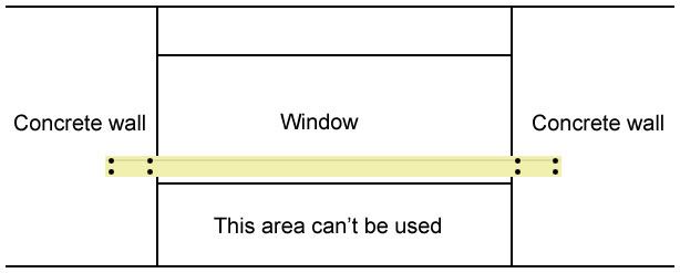
That leaves the wall.
Concrete.
Unless you pop a Hilti stud into it, with a red or green load behind it, you’re going to drill it. Hilti stud, drill, either way, you’ve already done all the work setting up the fasteners, regardless of what you hang from them.
Some folks like metal studs. I’ve torn too many of those out to have much respect for them. On ding, one twist and it folds up like an accordion.
Now a big heavy two by, well I’ve torn a bunch of them out too. Piece by piece with the rest of the building in place around it. Brick ledge unnoticed by layout man, three floors worth of staircase, two bathrooms, and two closets, plus one corner of four rooms worth of joist systems on two floors, 4 and a quarter inches out of place. I had to respot a ridge prop and a valley prop (carrying a half a 37 foot Microlam) too.
If I have to tear it out, yep, I choose the metal studs. But at my house, I just don’t put stuff up to tear it out later. Once I decide it needs to be there, well in a couple hundred years, if somebody else wants to remove it, they can take their chances with a slege hammer, a spud bar, or a case of 40 percent. (Ok a smart guy would back the lags out of the expansion inserts, but that’s not the point.)
Maybe just a difference in philosophy?
Perhaps.
In any case, if dead load was an issue, I wanted tough and light both, I’d scout residential construction area, upper middle class, not the 120K crackerboxes, not the multi mill mansions, the 50th tothe 75th percentile between those two points, looking for something that looks like a wooden I-Beam, call it a two by two for the flanges and a piece of half inch plywood for the web.
They market them under the tradename “Silent Floor” over here, and we always used
Exactly !! If you prefer, you can also get them at Menards, Home Depot, Lowes or similar.
I will give you an example. My layout has one leg that goes 25’ down on wall. I have built a pair of L girders and they span 8’ 4" between cantelevered wall brackets. They hold up a raiload the extendes 24" - 30" wide and I can climb up and crawl on the benchwork - it is solid.
Jim Bernier
People, please remember that the person asking the question lives in Sweden – he doesn’t have a Menards, Home Depot, or Lowe’s store there, and probably doesn’t understand half of the terminology some of you are using.
Electrolove, an I-girder, which we here in the U.S. call an I-Beam, would be stronger than an L-girder (or beam). Whichever you choose, the fasteners are going to be the most critical factor to consider because they will be bearing all of the weight and can easily pull out of the wall if you don’t use the right type.
Are your walls solid poured concrete or hollow concrete blocks? The type of fastener you should use and the weight they can bear is going to depend on this factor more than anything else.
I would suggest that you try to find someone in Sweden who knows exactly how your walls are made and which type(s) of fasteners would be suitable and can bear the stresses. Unless you think you might lean on your benchwork, whether intentionally or accidentally, you should choose a fastener that can bear your weight plus that of the shelf. An I-beam made of hardwood, if properly fabricated, should be more than sufficient to support the weight of your layout alone without sagging. Metal would be stronger, but is going to be more difficult to work with.
Two important facts are missing.
What is to run over the proposed span? (Z, N, HO, O, G, Live steam or 1-1 scale)
How deep is the proposed span? (Distance from wall to furthest edge)
There’s a Finnish company that makes a girder you might be able to use. I would think they would also be sold in Sweden. Here’s their website (there’s Engli***ranslation available): http://www.teurowood.fi/
Here’s a better look: http://www.teurowood.fi/factory/eng2/
You could also make your own L girder using using 1x4 lumber for the the web and 1x3 lumber for the flange. It would have enough strength to span an 8 foot foot window without intermediate support. http://rail.felgall.com/lg.htm
Andre
Extruded aluminum “U” channels combined w/ plywood should cover the span if a smaller profile is desired.
You are absolutely right about that. I don’t have any of the stores that you guys have. And the language does not make it any easier for me. Sometimes I can’t get into any advanced discussions because I just can’t explain what I mean in your language. That’s the reason I love pictures, pictures is a universal language. And I think pictures is the best way for all beginners to learn as well. So if you guys want me to understand, please draw a simple picture. It does not have to be fancy in any way. But even if I have problems with your language from time to time, I have learned a lot since I joined this forum. And that’s because there is so many helpful modellers here that answers the same basic questions over and over again.
Thanks for pointing that out cacole.
electrolov, if you have access to a copy of Basic Model Railroad Benchwork by Kalmback books, page 32 has a table that indicates the maximum load bearing spread different L-girders can support. Page 71 also has some ideas on methods of wall mounting with concrete and block walls.
If not, email me below, and I’ll get you the info.
Actually, what is shown is NOT a cantilever. A cantileverd beam is one that is attached at one end only and restrained from turning, but the opposite end is free of supports. The diving board example is exactly right as a catilever.
What electro is asking about is a “Clamped Beam.” Each end is fastened in such a way that it is clamped against rotation AND deflection. This over-constrained beam is VERY strong, since the zero-bending point is located about 1/4 of the way from the attachments on either end.
Unless you’re going to be applying several thousand pounds of load to this thing, an L-girder made of a 1X4 web with a 1X2 flange on top will be more than sufficient.
By the way - someone else said that an L-girder will not deflect before it breaks if it’s properly designed - this is incorrect. Even a light load will deflect any beam, as the beam must develop strain energy to counter the load. The question really is if the deflection is sufficiently small for a given load to be of no consequence.
Electrolove:
To see what a wooden I-Beam, or what jeffers_mz was referring to as a “Silent Floor” member, just go to Craig Bisgaier’s website. He’s got a section on building such beams himself, complete with pictures. The section I’m referring to starts at: http://www.housatonicrr.com/ibeam.html
You might find the rest of his site interesting as well. When it’s completed, it should be a great railroad. The home page is at: http://www.housatonicrr.com
-Ed
The cantilever principle is utilized in a clamped beam, but you are correct, technically a cantilever will have a free end. Even a cantilevered bridge has a complicated series of expansion joints at the join points between two cantilever sections, so that each is physically an unfixed point in space, at least in the vertical plane.
“Keep it simple”, “not technically accurate”, finding the zero point is an exercise in placation, across a broad spectrum of percepti
QUOTE: Originally posted by jeffers_mz
The cantilever principle is utilized in a clamped beam, but you are correct, technically a cantilever will have a free end. Even a cantilevered bridge has a complicated series of expansion joints at the join points between two cantilever sections, so that each is physically an unfixed point in space, at least in the vertical plane.
“Keep it simple”, “not technically accurate”, finding the zero point is an exercise in placation, across a broad spectrum of perception.
Bullet proof: “Spread the fasteners, some near the window, some back away from the edge. This will allow the beam to carry more.”
Though a clamped beamd a cantilevered beam may look similar, a cantilevered beam behaves very differently from a clamped beam (or from a simply supported beam, for that matter). The shear, moment and deflection diagrams for the three beams is very different, and selecting between them is in no way an exercize in placation.
This site provides moment / shear / deflection diagrams for common (and not so common) beam arrangements:
http://ss.marine.osakafu-u.ac.jp/~masaoka/struct/beam/
Electrolove has picked the attachment method that will minimize deflection of the beam and maximize its load carrying capability, and you are right on with your “Bullet proof” statement.
Can you give an example of a cantilever bridge? I don’t believe I’ve ever seen one, but maybe I have and didn’t realize it. Bascule bridges, when the span is taken as a single beam, might be seen as cantilevered when lifted, but when in place and carrying load, even they become simply-supported beams. In fact, the only bridge type of which I am aware which is not simply supported is a suspension bridge.
Non-confrontationally, [:)]