Lol, I just realized that the tittle’s font’s capital I is the same as the lower case l. Anyways…
Hi everyone! This is going to be my first instructional post!
How to Illuminate a Walthers passenger car
Materials:
LED strip w/ adhesive backing(Off Ebay for $5)
2 rail joiners
Capactiors(optional)
thin wire ( I used 30 gauge)
solder
1. Open your Walthers passenger car using whatever method you want. I used the twist method.
cut a strip of the LED strip to the length of the roof.
cut 2 3" strips of thin wire and remove the insulation from the ends.
Solder the wires on to the light strip.
push a small screw driver through a rail joiner. Then pull it off the screwdriver via pliers and squeeze the rail joiner flat. This is so it is wide enough to fit on the 2 electrical contacts.
Slide them on the contacts. Make sure that they are snug.
Optional: solder a capacitor in series into the circut. This will make it not flicker as much when running over dirty track. (I did
I like your idea of the rail joiner on the Walthers contact strips. Those strips are plated steel and impossible to solder to (without actually removing them from the car) I found some very small crimp terminals that work but I like your idea better.
I have used several of the LED strips in my passenger cars and they do need a resistor to reduce the intensity of the light. (I don’t recall the value off hand)
Looks great, but I think you’re on DCC? An install on DC would be different. This is my DCC install circuit.
I use a small bridge rectifier on my LED light strip installs, with a cap across the leads from it to the light strip. Like this:
Part number for the bridge rectifier is noted. This gives straight DC to feed the LEDs.
I suspect yours works without the complications of mine because it’s a half-wave circuit: only one side of the square waveform feeds your LEDs, which have to be fed correctly polarized. I suspect your lighting isn’t continuous, but flickering so fast the eye can’t follow, so it looks like constant on. I tend to use what I think is your circuit where space is at a premium.
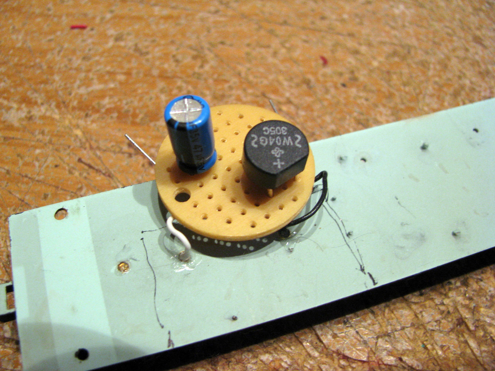
Whatever works is my approach. If you do find need for the circuit, here’s one version on a circuit borad that shows the components well.
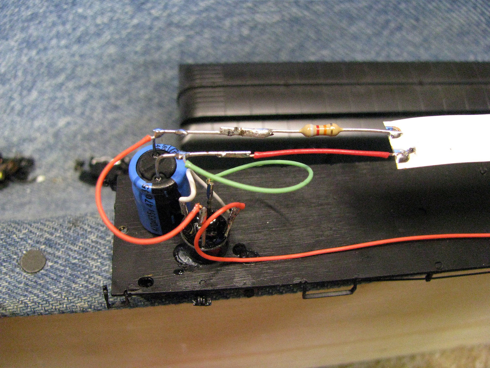
This one shows how I do most installs now, with the components free-standing where I can find the space. This install is going into a HOn3 brass car, similar to where the above circuit board mounted one went (it was in a parlor car.) Lots of empty space, but few windows in this car made things easier.
A note in the caps…It’s a 470 uF illustrated, but I’ve had success in killing flicker with ones as low as 47 uF, which is much smaller. The 470 does allow decent run time off the track for looking at interiors, etc[I]
Mike- Im sorry, but what is the bridge recifter for? I wanted to wire a capacitor to my circut, but everytime I applied power to the tracks, the layout would restart. I think the NCE power cab thinks that there’s a short in the layout. Possibly, the capacitor goes over voltage upon start up? And the controller is reading it as a short? Is that what the brigde recifter/resistor for? Am I right?
The bridge rectifier takes the DCC waveform (which is similar to AC, but it’s not) and rectifies it to DC, which is what LEDs like. Doing without the bridge rectifier means that the LEDs are only being lit when the waveform is positive at the positive at the positive lead. When it goes negative, then the track power does not feed through the LED, which allows power to flow in only one direction. It happens so fast that the LEDs look like they’re lit full time, but they’re not. I have a snowplow fitted with lights this way.
Yours still works because of that effect, sometimes refered to as a half-wave circuit, because you’re depending on only half of the wave to power it.
What you get as DC output depends on what voltage is fed via DCC. A typical setting is around 14 to 14.5 volts on the track. Mine is dialed back to 12.5 volts to help my Tsu-750s run cooler and make Athearn micro bulbs last longer. Going through the bridge rectifier drops it another volt or so. Thus the LEDs see around 11 volts.
Many DCC systems see a capacitor wired in series with the LED load as a short. You can get circuit breakers that are smart enough to recognize the difference between this brief inrush of current at start-up and how a short acts. That may solve your issue, I’m not sure. I have them on my layout, so can’t tell you how they act without it.
However, putting the cap across both leads is the way that antiflicker circuits usually work (th
Ohhh… ok, thanks Mlehmen [:D] Oops, I meant wire the capacitor in parallel. (Lol, I got series and parallel confused) Gotta change that in the post [:-^] So what I meant was when I wire a capacitor in parallel to my circut, it still shorts out the layout. Is that because of the half circut?
BTW my Panasonic Lumix camera doesn’t pick up the flicker from the half wave circut, and my eye dosen’t see it either, though when those cars are on the track, they do make a buzzzzzzzzzzzzzz…
Yes, All Walthers passanger cars that wern’t the kind that was a kit made out of wood and steel have built in electrical pickups in the car. Maybe that’s why they are so expensive.
How do you dial down the voltage from the power supply (DCC)? I have a Digitrax Zypher and believe it is around 14 volts. Most of my Athearn Genesis locos have burned out headlights (gradually replacing with LED’s).
Here is a link to a recent post on flicker free passenger car lighting. You will see that there is a 150 ohm resistor between the rectifier + and the capacitor +. The purpose of the resistor is to limit inrush current to the capacitor so that your DCC system won’t see the capacitor as a short circuit.
With NCE, it’s in the Command Station Settings menu. Probably something similar with Digitrax? Maybe someone knows for sure who is more Digitrax-fluent than I am.
Note that if you have various lighted equipment dialed in just right at the higher output voltage, they will dim some when you turn it down. This is usually for the good with them, too. In my case, I did this early on in my DCC life, so everything I wire up comes out where it needs to be at the lower voltage.
For what it’s worth, I just purchased the components from Digi-Key. The capacitors aren’t exactly cheap but if you only buy what you need for the number of cars you have its not too bad.
I have used a variation of this circuit designed by Mark R. in my caboose fleet and it works great. However, it used a 5.5 volt capacitor and the capacitor relies on the resistor/LED arrangement to avoid blowing itself up due to the track voltage being higher than the capacitor’s rated max. Wisdom’s circuit seems to make more sense because the capacitor will be safe regardless of whether or not other components fail. Don’t quote me! I know precious little about electronics![D)]
Dave got you a little more help with this. I suspect that without the voltage regulator in front of the cap, yeah, it thinks there’s a short.
With my half-wave install, I put a standard diode in each leg of the circuit. A bridge rectifier is a set of 4 diodes and does essentially the same thing, just with some redundacy.
Slight warning: If you don’t use a rectifier, and you run on standard 14.5 or 14.25 DCC voltage, you risk dramatically shorting the life of your LED or even possibly blowing it out. The resistors used are for 12V circuits, not 14.5 or 14.25. A bridge rectifier will cut that down to 12.5 to 13VDC which is within the 10% tolerance limit.
The LEDs create around a 3.5 Volt drop (give or take) after you rectify the voltage, you have 14.5VDCC (Track) - 1.5 (rectifier) = 13VDC. That’s enough to light 3 LEDs in series)
9.5 = Current * Resistence.
You have three options
Add 1 resistor to the entire circuit. But the math behind this gets complicated and you could overshoot your resistors max power rating easily.
Replace the each resistor on the LED strip. This is a lot harder to do.