I posted this recently on another thread about train detection, but I thought it might be good to bring direct attention to it be starting a thread all on its own.
This is a very inexpensive infrared train detector which will work with the layout room lights either on or off. In its basic form it is limited in what it can do. For example, there is no delay mechanism so the detector will turn on and off as each car rolls over it. Adding delay circuitry is beyond my comprehension but perhaps someone with a better knowledge of electronics could contribute that sort of additional information. It is also only capable of powering an LED, but I’m sure a relay could be added.
I must state a couple of qualifications: First, I have only used this circuit in test mode because I don’t have a layout to try it on. However, I have built three of the sensors and they all work. They will consistantly detect at about 1 1/2".
Second, I have no clue about where I got this circuit from so I cannot give proper credit to the designer.
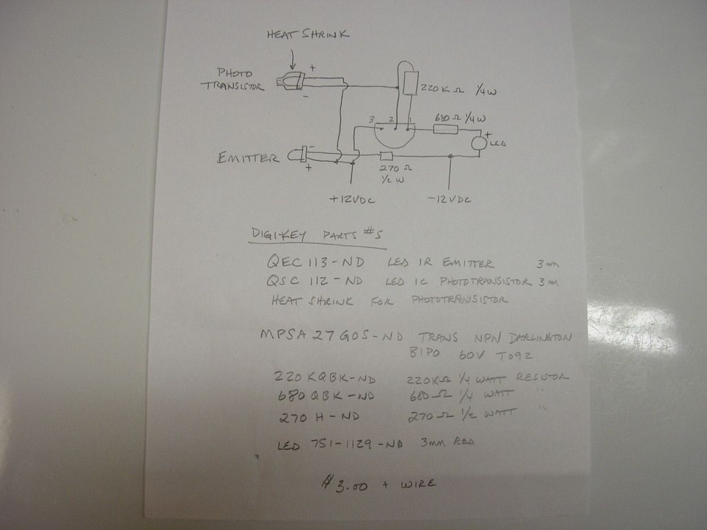
Here is the schematic and Digi-Key parts list. I think you can use pretty much any LED you choose:
EDIT August 3, 2013. Two key items in the above diagram have become obsolete: For QSC112-ND, use 160-1030-ND or QSD123-ND. Bob Frey whom designed the circuit recommends the 160-1030-ND but either will work. For QEC113-ND, use 754-1600-ND. All parts numbers are Digi-Key.
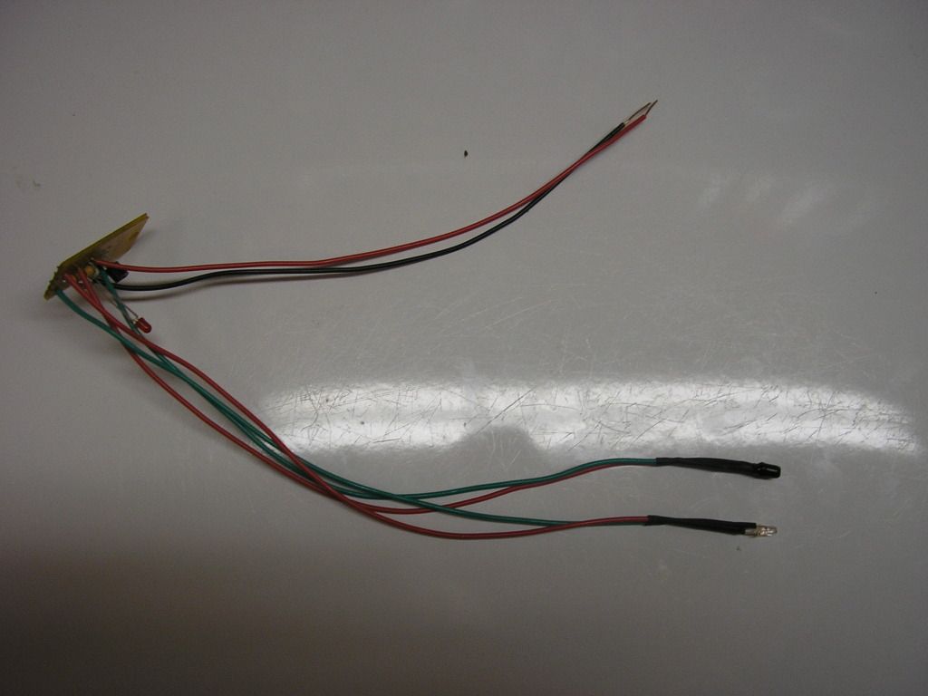
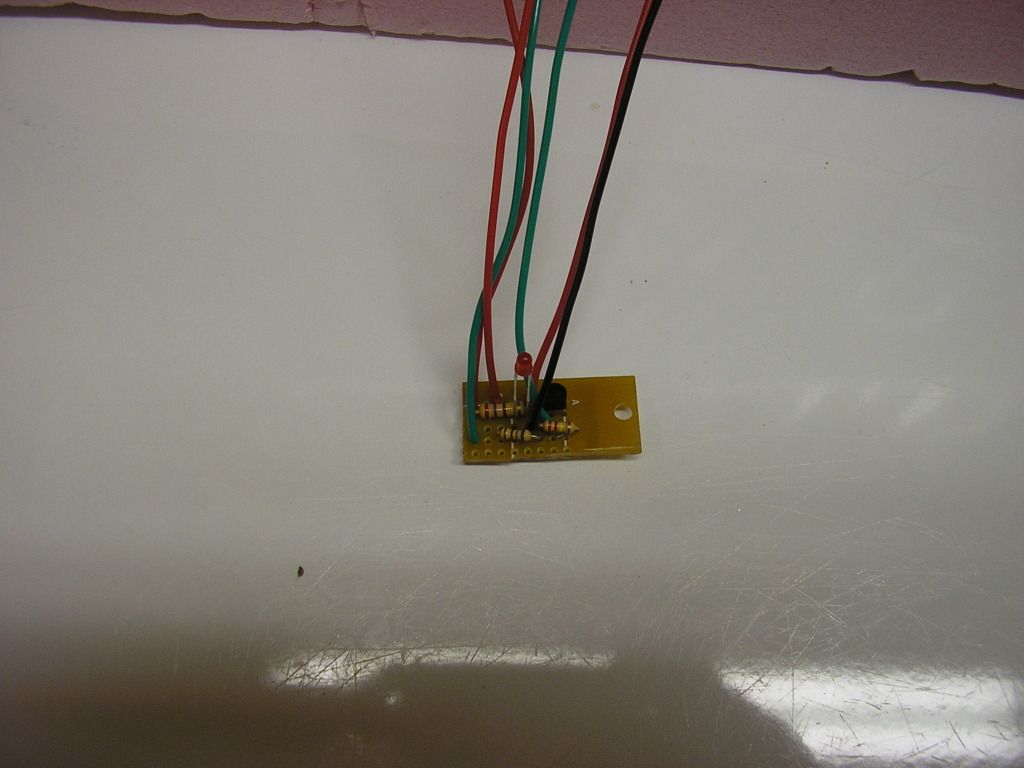
Here is one of the test circuits, as well as the test track. The tubes in the test track holes are heat shrink tubing:
Interesting circuit, but it labels +12V and -12V as the primary feeds. That would imply a balanced power supply. I think the -12V is supposed to be ground/common to battery.
I was using a 12V power supply so all I was trying to show was which way the leads were connected. Like I said, I am no expert in this stuff so I apologize if I have labelled the drawing incorrectly. All I know is that the circuit works and the price is right.
I may have to try one of these. I need just very basic detection, something to tell me – Am I clear of a point needed to provide room to turn a train on a wye without bumping the train staged on what is effectively the wye’s tail track? Looks like I may be able to find parts at Radio Shack. Will post 'em if I have any luck.
I got the parts from Digi-Key but that adds a shipping charge to the cost. For me (in Canada) the Digi-Key shipping charge is a bargain ($8.00 CDN to the door usually the next day - incredible service!). I hope that Radio Shack can supply the parts for you. I don’t think there is anything wildly unusual required. As I have said before, you will need a filtered 12V power supply. If you don’t have one then you should consider the small investment required as a good use of funds because you will be able to use the power supply to run a bunch of other circuits. The draw from the detector is peanuts.
What I didn’t include in the cost for the test circuit was the circuit board, but that is not a necessary component. You can build the whole thing and just use a bit of heat shrink tubing to separate the bits.
Good luck. Thank you for your interest.
Please do let us know if the circuit works for you. All the commercial stuff is way more expensive (granted they also have more features) but I think this is a gem that will suit many people.
By filtered DC, I assume that’s the same as a regulated DC source?
BTW, I also wonder about operation at voltages lower than 12 volts, although that something I know I’ll need to experiment with. Maybe one of our electronic gurus has a suggestion about that>
A regulated supply would be filtered. However, a filtered supply wouldn’t have to be a regulated supply. Filtering means that a suitable capacitor has been added after the diode(s) to smooth out the DC. A simple AC transformer-diode bridge-capacitor circuit would be an example of a filtered, non-regulated supply.
The voltgae would have to be around 12V, give or take a little bit, so regulated may not be needed. To operate on a completely different cupply voltage, like a 9V DC supply, the values of the resistors would need to be changed. I calculated my last transistor circuit more than 25 years ago so off the top of my head I don’t know what those values would be. Heck, 9V might even work as-is, but not any lower - testing a lower voltage to see if it works won’t damage anything, just don’t test OVER 12V. Worst that can happen if the voltage is too low is either it won;t light the LED or it will always stay lighted. Much lower than 9V and definitely that 680 ohm resistor connected to the LED will need to be reduced.
while i’m sure the circuit works as tested, i have to ask if the load driven by the circuit shouldn’t be more conventionally on the collector side instead of the emitter side if the darlington pair?
the circuit on the left in the drawing below is what i believe is the circuit as proposed. I suggest that a more conventional approach would be the circuit on the right. One issue is the the load voltage, the LED/resistor in the drawing but possibly a relay, affects the voltage across the 220k bias resistor in the photo-transistor path. I believe the circuit on the right makes the photo-transistor path independent of the load.
however, i can see the need for some hysteresis, to partially latch the circuit on or off, which the proposed circuit may provide, but which i don’t understand.
I think I understand what you are suggesting, but let me see if I have it right:
In the original design the position of the red LED/ 680ohm resistor (would this be called the load?) influences the amount of power going through the sensor/transistor part of the circuit. If a different load was applied, i.e. the LED/resistor was replaced by a relay, the sensor/transistor might not work properly.
In your revised circuit, the load (please pardon me if my terminology is not correct) will not affect the sensing function, assuming it is within the limits of the power available and within the transistors’s load range.
In other words, different devices could be powered using your circuit - yes? no? For example, could I use this with a latching relay to throw a turnout?
The way Greg redrew it, you could even thoeretically use a different power supply for the load. A latching relay though, well, you’d need something else to turn it off. Any load within the current capacity of that Darlington transistor would be fine though. If the load is inductive, like a relay coil, it should have a regualr diode paralleled across the coil to prevent the inductive kickback when it releases from causing a damaging voltage spike in the transistor.
You COULD rig a latching relay with a normally closed button to make an auto-stop for a hidden siding - when the sendor is covered, the relay trips and cuts track power. To get the train back out, you press the button to cut the relay power until the train has moved enough that the sensor is no longer blocked. As long as the sensor is far enough away from the bumper so that the coupler doesn;t hit before the carbody blocks the sensor, and you don;t barrel into the siding at warp speed, it should easily stop without crashing.
yes. i believe you understand the point i was trying to make. and Randy made some very good points. But i’d like to make 2 additional points:
don’t know if you understand how transistors work. The base-emitter (BE) path, the one with the arrow has characteristics of a diode. if the voltage across the BE is greater than a diode drop, ~0.7 volts, the transistor begins conducting. In the Darlington case, there are two diode drops, so the voltage at the base of the darlington, the lead on the left side of the circle, needs to be above ~1.4 volts. The 220k resistor is pulling that voltage down and the photo-transistor is pulling up when active.
one question is how distinct is the voltage change at the base of the darlington when there is light or no light? This determines how reliable it switches, and this may be why the load, the LED and resistor, are where they are. but i don’t think so. It would be nice if the light level needed to be a little higher to turn the circuit on than it needs to be to turn it off (hysterisis).
the circuit is active, the darlington is conducting, when the photo-transistor is active, hence when the light path is not broken. This may not be desired, it may be more convenient to to have something pass current when the light path is broken by the presence of a car.
another approach is to swap the positions of the photo-transistor and 220k resistor. This way the photo-transistor actually turns the darlington off instead of on. This way the the circuit become active when a car is present.
Actually a good “how do they work” was in MR back in the early 60’s, an article by Linn Wescott, of course. Naturally it was all about Germanium tranistors, but the principle is the same. Or there are tons of web pages, even the Wikipedia article, if you really want to learn a little about this stuff.
I think that also fairly simple circuit from MR a while ago (correction posted here - as drawn int he magazine it was wrong) is the opposite type - turns on the load when the bean is broken, vs this one that turns off the load when the beam is broken. Or check out Rob Paisley’s site, he’s got a million of them. Don;t discount some of the ones that on the surface appear more complicated because they use an IC - some of those eng up with 2 or 4 detectors from just one IC - in the long run even cheaper than these simple transistor circuits.
I may build some of those, but get some panel mount meters, cheaper than a RRampmeter. Depends on where I end up before building my ‘dream’ layout - depending on the room size and track plan it will probably make more sense to distribute boosters around the layout than have long heavy bus runs from some central power panel. Master power panel with meters and stuff would look cool though.