I know from reading walthers curved turnouts are a bit of a lie just wondering if the same is also true, they are listed as 30" and 22"
This discussion was open on an another forum.
It seems they are not, the real radius are somewhat smaller because the method to calculate the arc seems somewhat obscure; the diverging arc is not a composite of the first arc but an arc used to be compatible with the rest of the geometry Atlas use.
Same remark can be done with Peco track and finaly all the brand of track which are offered on the market.
The best to do is draw them and see what is really the arc, to estimate and draw the needed radius.
But anyway you must live with these radius and all the geometry of the Atlas track system is done to work with these radius.
This is important if you desire to use the full Atlas geometry, but you can go out with ease and have a natural flowing track using these turnouts but going out of the Atlas geometry
If you are asking to have flowing track, may be make a try to the yardstick method.
In fact each group of turnouts or a lone turnout is connected by a piece of track; this connection is straight or curved following your desire and your plan.
The yard stick is a thin piece of wood with a lot of flexibility.
You attach one end at the edge of the ouside track of the turnout with some nuts and slowly you flex the yardstick slowly to reach the next turnout or group of them and you drawn a line along the yardstick.
You have now an extremly flowing track between the turnouts with natural easement and with no care of inside and outside radius from the coming turnout
Just check if the radius is not under the minimum radius you ask to use and you can lay the flextrack to join everything together.
The yardstick work for opening a radius or close it further in the curve
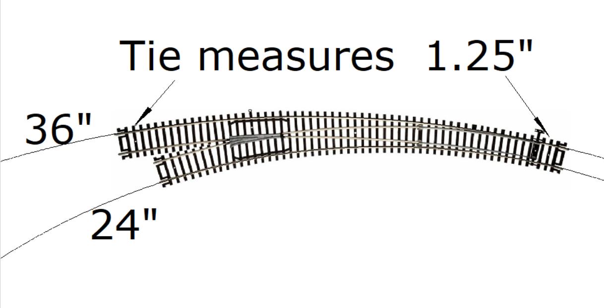
I took a picture off Google Images of an Atlas 595 and did an insert into my CAD. I sized the picture using the length of a tie and came out with inside curve 24” and the outside curve 36”.
Mel

My Model Railroad
http://melvineperry.blogspot.com/
Bakersfield, California
thats know where near what they say why caint any of these manufactures label things the right way.
[quote user=“RR_Mel”]
I took a picture off Google Images of an Atlas 595 and did an insert into my CAD. I sized the picture using the length of a tie and came out with inside curve 24” and the outside curve 36”.
Mel
My Model Railroad
http://melvineperry.blogspot.com/
Bakersfield
Yes but you are talking about less than a ½” and my drawings are only close to accurate not knowing the length of the turnout. Using the width of a tie for reference only gets the radius in the ballpark, if the published Atlas pictures are accurate my dimensions should be within a ½”.
EDIT:
I used the same process on Peco curved turnouts before I bought a pair to see if they would work for my needs and when the turnouts arrived my drawings were within a 1/16”.
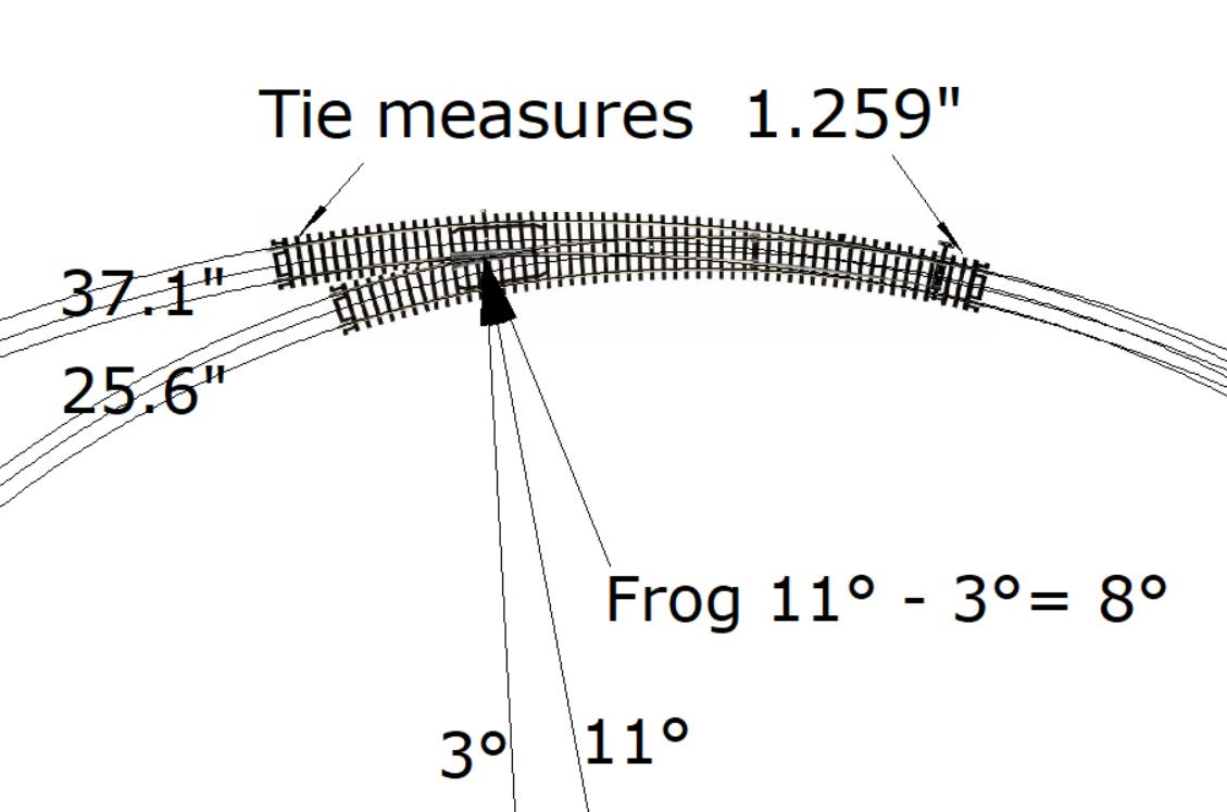
The 24” & 36” are only close, the radius to center track measurements are actually 25.6467” & 37.1892”
[quote user=“RR_Mel”]
Don Z
Mel,
Wouldn’t the actual radius be measured at the centerline of the curves?
Yes but you are talking about less than a ½” and my drawings are only close to accurate not knowing the length of the turnout. Using the width of a tie for reference only gets the radius in the ballpark, if the published Atlas pictures are accurate my dimensions should be within a ½”.
EDIT:
I used the same process on Peco curved turnouts before I bought a pair to see if they would work for my needs and when the turnouts arrived my drawings were within a 1/16”.
The 24” & 36” are only close, the radius to center track measurements are actually 25.6467” & 37.1892”
when i studied curved turnout geometry for building my own turnout, i couldn’t understand how the frog of commercial turnouts were so close to the points. What I found was that this is the result if the curves actually start of different locations
so when looking at commercial curved turnouts, you may need to account for this when measuring the curve radii.

OK, a few facts, a few thoughts.
First I cannot speake regarding PECO, but Atlas Custom Line Turnouts, including the new curved turnouts, are not designed to fit into any sectional track track system of curves. Atlas has no sectional track curves that large.
Side note, yes the straight Atlas Custom Line turnouts do have a geometry that makes crossovers and yard ladders without cutting, but they are straight frog North American geometry and the diverging routes do not match any sectional track curves.
Now that we have that cleared up, the radii chosen for most model curved turnouts is based on a few simple facts.
The main two reasons are simple:
First both radii need to be in a range useful to a large number of modelers…
AND, the two radii need to be different enough to create a frog angle that is sharp enough (low number) to be reliable under NMRA track standards.
Is anyone selling #20 HO turnouts? No, the frog would be too long and would require an operating closing frog in HO.
So the inner route of a curved turnout must diverge fast enough to create something in the range of a #6 (9.5 degrees) or #8 frog (7 degrees), and surely no more than a #12 at just under 5 degrees.
Turnout frogs above #12 can be problematic with regualar NMRA standard wheels/clearances.
You think you have some wheel drop now with semi scale wheels - that’s why I don’t use them…
So there you have it, the inner radius has to be enought smaller to give a sharp enough frog angle - period.
And yes, the inner curve need not begin on the same radius line as the outside curve, remember, on a prototype turnout, the points and the frog are both straight, points don’t curve away, they change direction at a straight but shallow angle.
I have made very large outside radius curved turnouts by simply cutting the tie webs of regular turnouts and bending them.
Sizes like 36" radius and 60" radius.
Greg
Would this be correct for the Atlas 595?
The turnout shown above is a JPG from Google Images of an Atlas 595 Turnout using a code 83 tie for reference.
Mel
mel
could you overlay 30 and 22" radii curve onto the image?
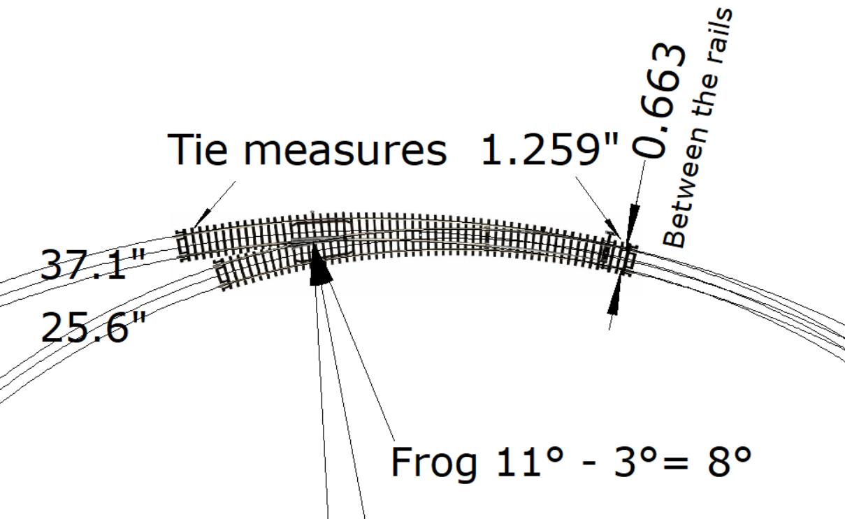
instead of using the tie length for reference, could you use the distance between the rails? the spec is between 0.649 and 0.672", 0.660"
i don’t believe modelers are trying to replace sectional track with curved turnouts, but they do need to know the radius and where the center is
without offsetting where the curve starts, the frog ends up being a long distance from the points making the turnout pretty long. Even then, the frog # isn’t too large. (i figured out the offset thing after i built the turnout)
Greg
The dimension between the rails on the JPG in my drawing is .663”.
EDIT:
The 37.1" & 25.6" are the measurements to the center
Mel
My Model Railroad
http://melvineperry.blogspot.com/
Bakersfield, California
I’m beginning to reali
Marc suggested the sizes were selected to fit into brand specific track system geometries, not so in the case of Atlas, very true in the case of other/older European
here’s a comparison of curved turnout geometry w/ and w/o a shift in the starting point of the curve. W/ the offset, a #7.7 frog is 10.1" from the points and w/o the offset, a #8.1 frog is 12.2" from the points. I wouldn’t be surprised if the offset is greater. a 2" offset results in a #6.5 frog only 8.7" from the points


Again agreed, but that is also effected by radius, and radius differential.
And by which curve is considered primary and which one is considered diverging.
No doubt the study of a wide range of combinations my prove very interesting. But operationally I think it is always better to consider curved turnouts as diverging outside a minimum curve rather than diverging into a tighter curve.
Sheldon
with a regular turnout, which path is considered diverging? which path applies greater force to the wheels.
But we are not talking about a regular turnout.
If we first consider the wheel/rail relationship in a curve, where in theory we prefer the flange not touch the rail, but we understand it might, the wheel shifts to the outside, increasing the effective diameter on that wheel and steering the axle toward the inside of the curve.
Seems a lot more reliable to have the axle/truck/train in steering mode at a given radius and then relax it as if it is coming out of a curve on an easement rather than asking it to go into a sharper curve.
The likelyhood that possible flange contact would promote riding up at the points or the frog is thereby greatly reduced. Especially considering that no matter what we do, the points are also in theory a small but abrupt change in direction on the diverging route.
So, if we condsider the inner radius the constant radius, and use the curved turnout to diverge outside the given radius, all wheel relationships stay the same as inner curve or are reduced on the outer route, not increased.
With the turnout set to the inner route, wheel forces at the points do not change.
With the turnout set to the outer route, wheel forces move in the direction of less flange contact, not more flange contact.
Sheldon
isn’t more force required to accelerate an object along a smaller radius path than a larger one?
What does that have to do with this question?
The “given” is that we have a minimum desireable radius on the inner route to begin with.
On a regular turnout, thru the straight route, we are already at “best case”, and the diverging route will always be less desirable.
But with a curved turnout, we should make the inner route our “best case in a curve” or “minimum acceptable best case in a curve” and make the outer route a move toward the best case of straight track.
Sheldon
You seem to be making assumptions not in evidence about available space and possible radius.
If I set 36" as my minimum radius, I am not going to diverge off the inside of that with a curved turnout.
So if a curved turnout will solve a space issue, I will first position the 36" curve to feed the inner route, than branch off the outside to feed the outer route.
Sheldon