does anyone have a clear diagram of prr gg1 4903 as mentioned as prr locomotive chart showing all the parts in detail with labellings as the ones available on the net are blurred and tricky to go through.thanks
Kalmbach published a very good set of GG1 perspective ‘cutaway’ drawings showing the various subsystems in detail. (Classic Trains summer 2009?) As I recall, they were available on the Web for a while as part of a ‘package’ of articles.
2 Likes
This may not be 4903 exactly but it may represent others in its class. From an operators manual I have issued in 1940:
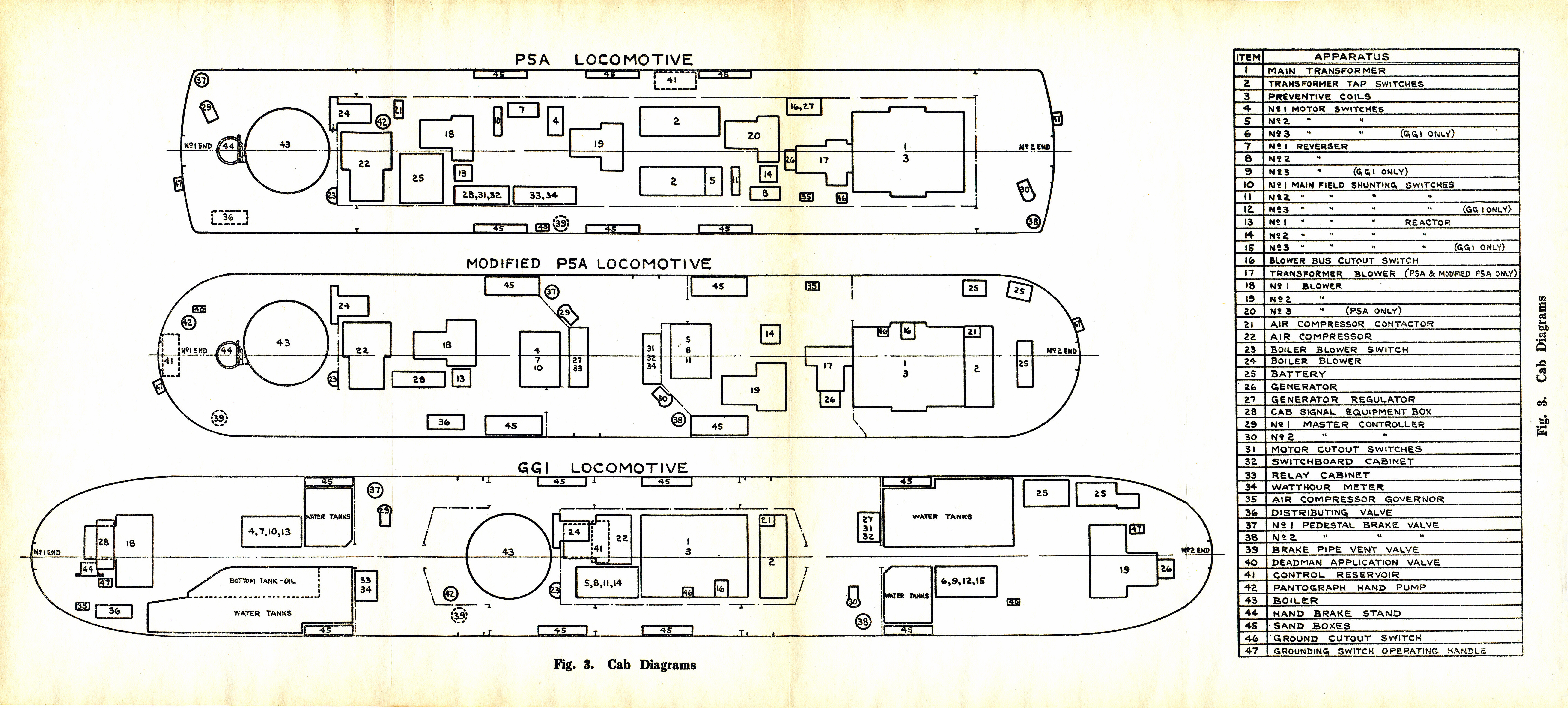 P5A GG1 Cab Layout by Edmund, on Flickr
 PRR Motors Cover by Edmund, on Flickr
 PRR Motors_0013 by Edmund, on Flickr
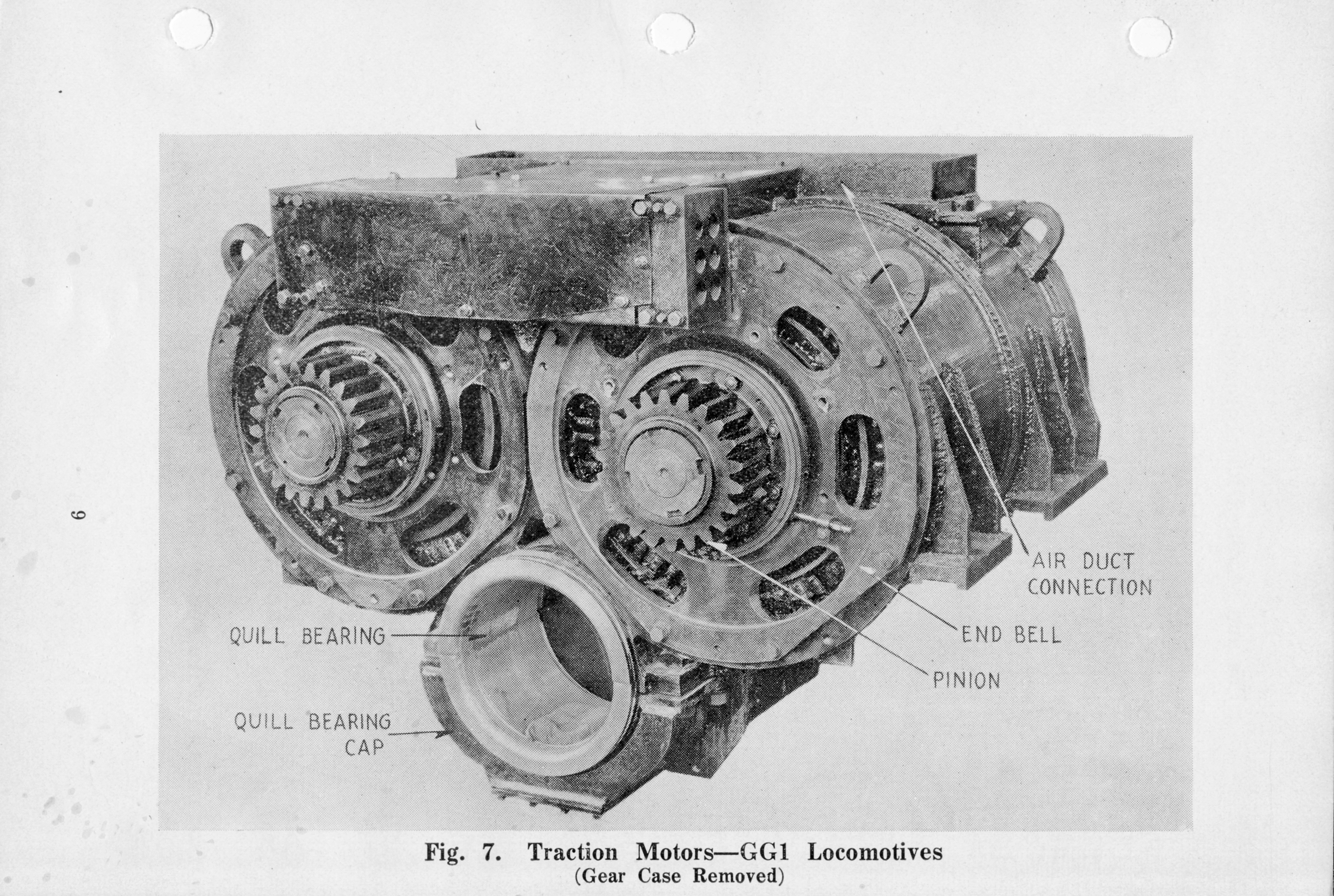
 PRR Motors_0005 by Edmund, on Flickr
I’ll be adding more pages as time permits to scan them.
The photo of 4856 in Futura Lettering is exactly 90 years old, as of this Friday!
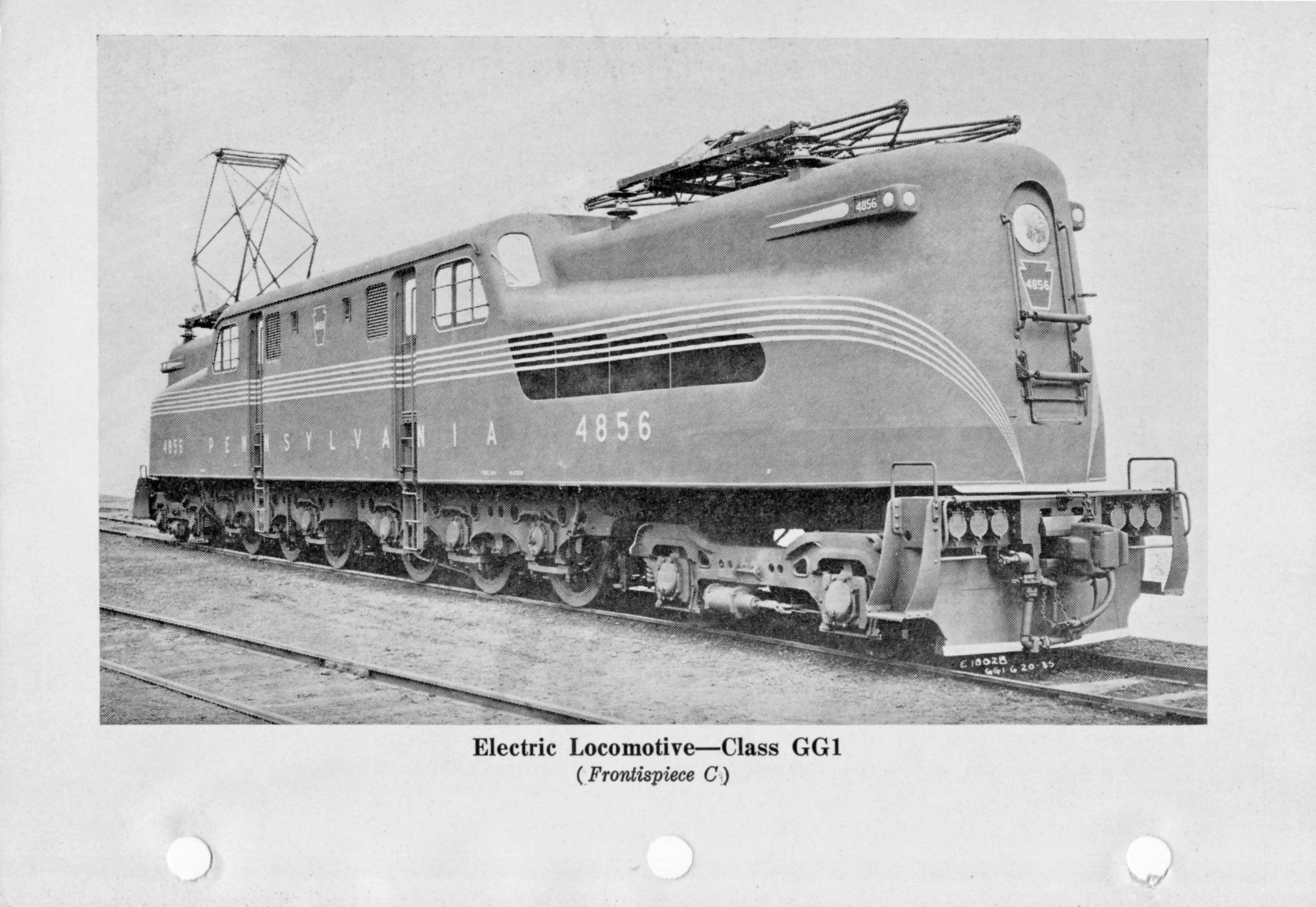 PRR Motor GG1 4856 by Edmund, on Flickr
Recards, Ed
3 Likes
thanks a bunch for providing the information,I am researching on gg1 locomotives and several older electric locomotives especially boxcabs in US regarding their whistles,horns,diagrams and pantograph control and I would also like to know if anyone has got a cab photo of the gg1 with labelling as I have already got a photo that came out with the trains magazine of summer 2009 showing several controls in the cab however that picture doesn’t have any controls perataining to the operation of the bell is it because older electric boxcabs and steeplecabs had bell cocks before switches became the standard after 1945 and if anyone knows why some early gg1s had a 3 chime air whistle that resembled a steam whistle probably Lukenheimer and mimicked the sound of steam whistles however quickly switched over to leslie a200 horns.Does anyone know how those air whistles would have sounded like.Kindly post it below.
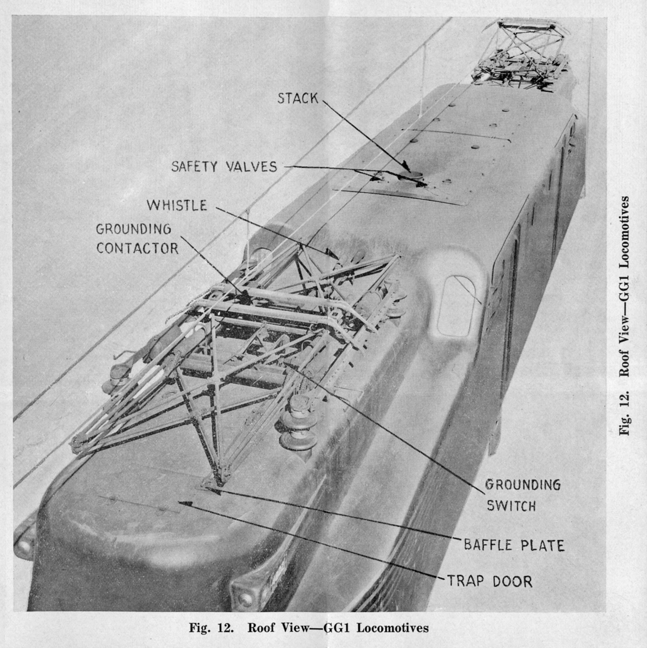
I was surprised when I saw the diagram of the GG1 roof showing the 3 chime whistle.
Closer view:
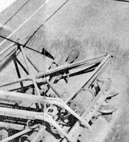 GG1_top_crop by Edmund, on Flickr
On my HO P5a boxcabs I chose the Hancock air whistle which is probably pretty close.
I’ll see if I have anything of the cab layout. The controller is an interesting arrangement, too, with its “buck and boost” notching. I’ll be scanning more pages of the Engineman’s manual as timer permits:

Regards, Ed
1 Like
Thanks a ton for sharing.I would like to ask you why this 3 chime whistle was present on early
GG1 locomotives especially the prototype and did it sound like a sound
a steam whistle on air.So why do you think some electric locomotives built during steam era from 1910s to 1920s/30s had steam like air whistles was it maintain a sense of auditory similarity among the people as they were accustomed to the sound of a whistle before horns took over.And what was the procedure to raise the pantograph and were there any selector buttons for each panto on the GG1.I’d equally like to know why did PRR used whistles on some GG1s from 1934 including the Prototypes such as DD2,R1 at a time when air horns were becoming common like Westinghouse pneuphonic types which were introduced as early as in 1928.
I would be surprised if this were something ‘other’ than a standard three-chime PRR passenger whistle.
My understanding was that the pans went up with springs and were pushed down with compressed air; surely this is in the Operator’s Manual that gmpullman has.
2 Likes
I had an intuition that the pattern in which the 3 chime air whistle sounded would have been comparable to Prr steam whistles on passenger locomotives as GG1s were made during the steam age ie during 1930s so they could have borrowed some auditory characteristics from steam locomotives although the inherent source was air to power the whistles slightly similar to how hancock made air whistles that emulated steam whistles although GG1 whistles resembled a lukenheimer whistle from outside.
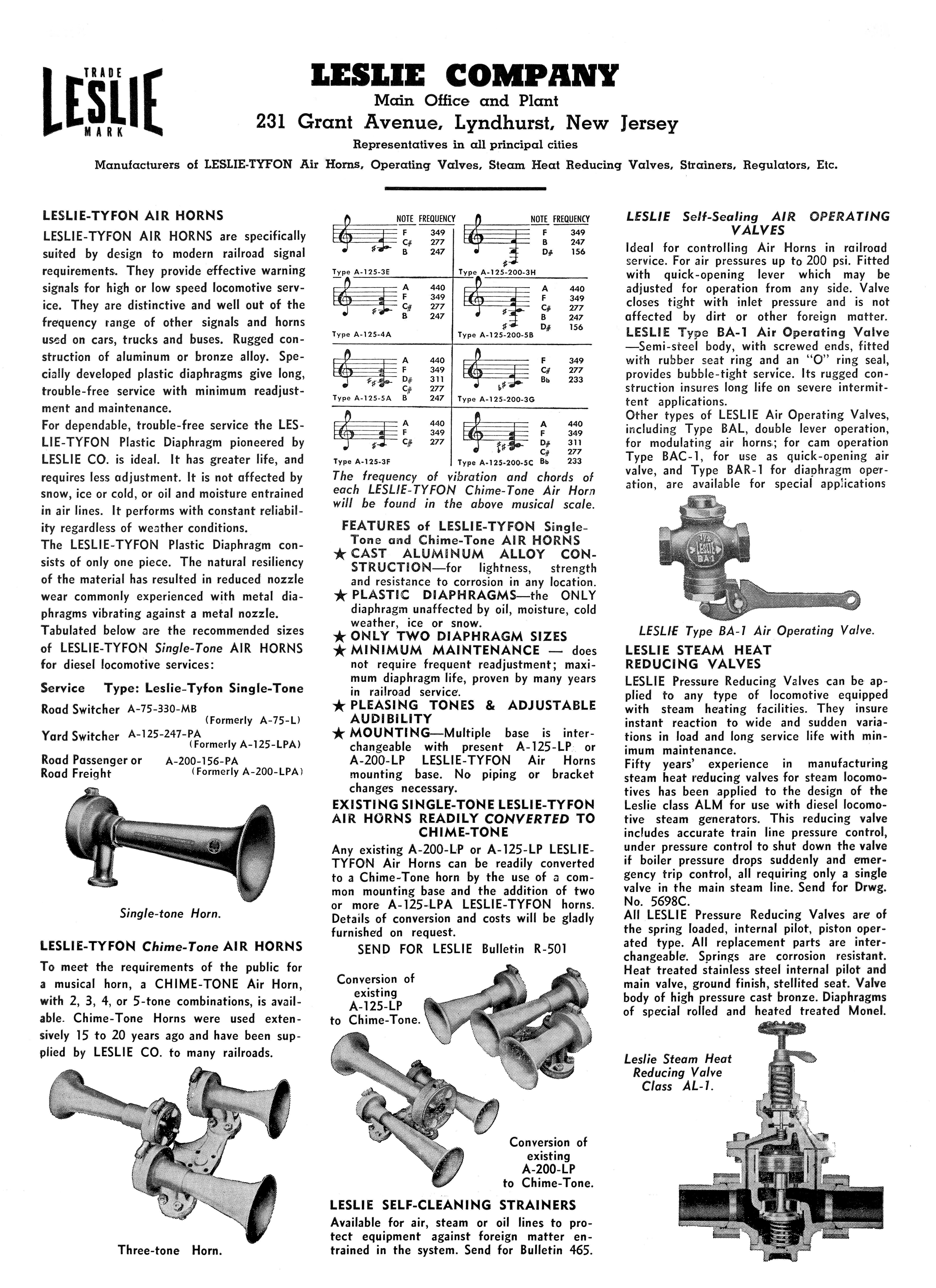
The Leslie Typhon A-200 was developed and still ‘experimental’ in 1934. Still ‘new technology’ at the time and early models had problems with nozzle wear and diaphragm materials. In 1935-36 they worked these problems out, mostly, and they were gradually accepted as being reliable. Many electrics of the time used air whistles as they were familiar to shops and railroad management.
 Leslie-Typhon_0001 by Edmund, on Flickr
Some of the P5as had a twin-note curved bell Westinghouse horn.
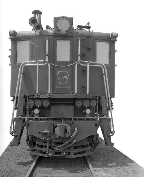 PRR_P5a-7898 by Edmund, on Flickr
Later they were fitted with the Leslie A-200s:
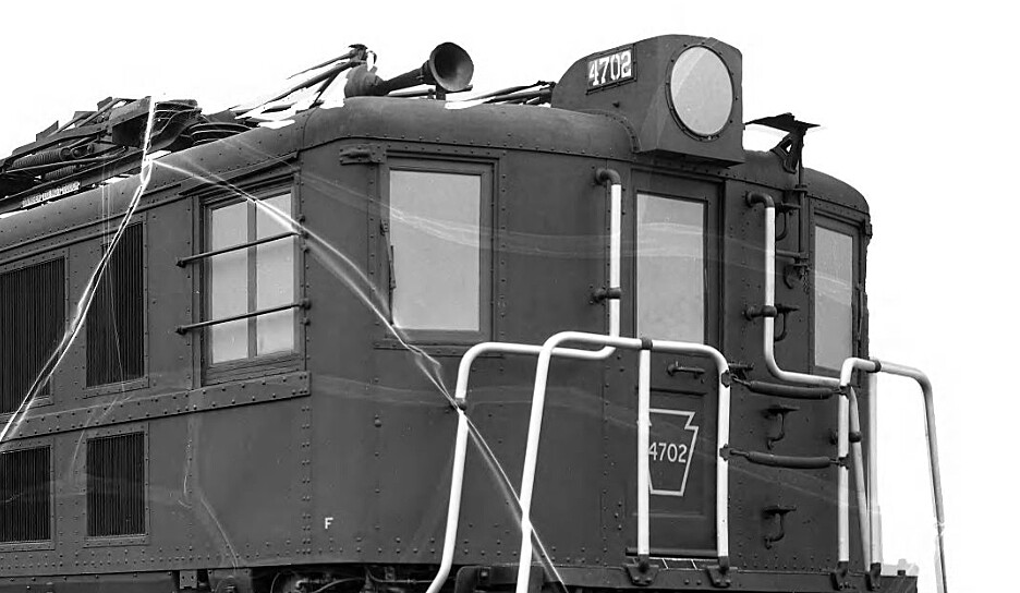 PRR_P5B_4702-a by Edmund, on Flickr
The whistles/horns on P5as were ‘magnet valve’ actuated, a precursor to today’s modern solenoid systems.
As train speeds increased there was more attention focused on ‘projecting’ the sound forward for better awareness at highway crossings.
Pantographs were spring actuated to raise to the trolley wire and air cylinders operated by ‘magnet valves’ (solenoids) were used to lower them and another cylinder to latch them down.
A wood pantograph pole could be used to raise or lower the pantograph if the air cylinder fails.
The P5a pans were connected by a jumper so if one pantograph is raised the other one is ‘live’ too. There is a grounding switch that is engaged when the pantographs are lowered and electrical work can be safely performed. There are baffle plates that close off access to the roof on the P5s or access to the roof trap door on GG1s.
Either, or both, pans could be raised. Sometimes one would get damaged and the other could be raised in order to continue operating. Usually in icy conditions both pans would be raised. The front one to primarily break the ice and the second one to collect current.
Good Luck, Ed
Thanks for giving this crucial piece of info.I’d like to know whether the buttons labelled as pan1,pan2 in the cab controlled the pantographs and was there a way to raise the pantographs and select which panto to be raised when the locomotive was started out of a shed with no air supply and if you have any info on the bell control cock of GG1 tell me along with who manufactured the lukenheimer like air whistles emulating steam whistles and have there been instances of electriclocomotivesduring steam era using 5 chime whistles or 3 chimes were the norm.And if you know where I can find cabs,diagrams of prr aa1,l5,l6,p5,odd b1,FF1,R1 electric locomotives if possible and feasible.
Regards
e44viv
There was a hand air pump which would raise enough air pressure to release the locking cylinder. Spring tension would then allow the pantograph to raise whereby the air compressor motor could then be operated.
The dead man pedal had to be depressed in order for the pantograph “up” or “down” button could be operated. As far as I can discern, the pair pf buttons would only raise/lower the pantograph closest to the operating cab. Therefore if the rear pan was to be raised the engineer or hostler would use the aisle passage and go to the rear cab.
The bell valve was a simple ¼" globe valve located just ahead of the independent brake valve. Nearly all the GG1 bells I recall hearing were pretty ‘muddy’ and dull sounding.
Faiveley on a G?
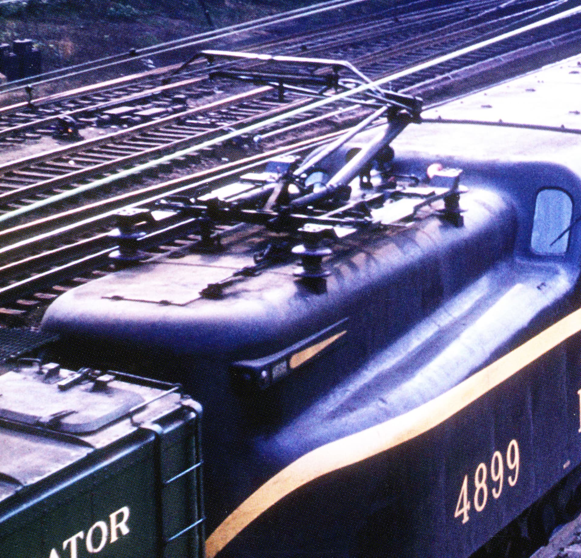
A crop of a photo by the late WD Volkmer. Dated October 16, 1960.
Regards, Ed
1 Like
Thanks a bunch,and anything regarding the location of headlight switches,cab lights,compressors and when they recieved windscreen wipers the wiper cocks and what is with the faivley pantographs seen on PRR GG1s and for the traction chain I beleive they used transformer taps with single phase motors for speed control.
I believe the Faiveley pan was a test for implementation on the Silverliners (the original 9000 series) but it certainly could have been related to E44 development. If I am not mistaken there were later tests of Faiveleys in conjunction with Metroliner development. (Ed will remember if there were comparable tests of the German Stemman pans…)
The Gs took over the ‘universal’ motors from the New Haven design; they were in part used as a cheap way to use DC to get New Haven trains into Grand Central Terminal. The complicated system of taps in the large main transformer is what ultimately killed the G rebuilding program; the transformer was built with Pyranol (made with the infamous polychlorinated biphenyls or PCBs) which allowed the use of paper insulation – there was no practical way to get the Pyranol out of all the paper, and it would have been much more wildly impractical to disassemble all those taps and replace the insulation with something that would work with the replacement fill materials…
Of course just a couple of years later PRR designed a better electric around the GE 428A twin motor (this was the DD2, higher continuous horsepower out of two fewer drive axles with 5" taller drivers) and the subsequent stillborn electrification plans up to 1943 used this or an equivalent motor. Instead they built more GG1s for wartime service, and after the War designs went in a decidedly different direction than cast under frames with twin-motor quill drive.
2 Likes
and how did the throttle and other controls differ among baldwin westinghouse built and general electric built units.
Some of the better cab interior photos show a pair of double-pole double-throw knife switches. The engineer could choose #1 or #2 end, or both, engage the deadman pedal then press the ‘up’ or ‘down’ button as needed:
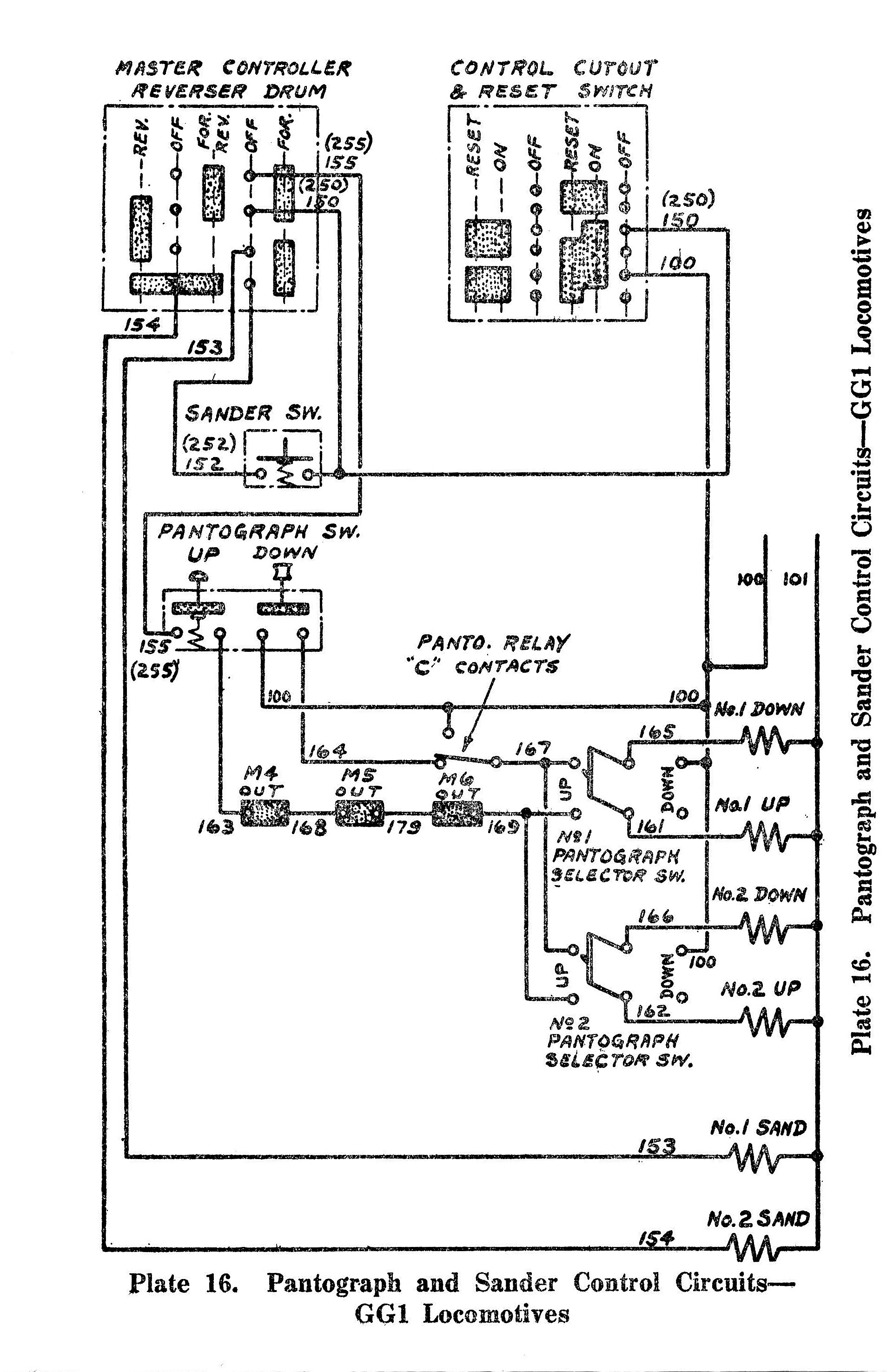 PRR GG1 Pantograph and Sander by Edmund, on Flickr
This may have been modified with removal of the ‘second’ knife switch in later years as any cab photo I’ve seen only has the push buttons and one knife switch.
Windscreen wipers were applied to all the GG1s from inception.
Regards, Ed
1 Like
I believe they all had the same drum switch Master controller. Westinghouse, GE or other I’m not sure exactly. Most likely Westinghouse.
 GG1 Master Control Circuits by Edmund, on Flickr
Indeed!
 GG1 Main Circuits by Edmund, on Flickr
I’ll have photos of both sides of the main transformer tomorrow.
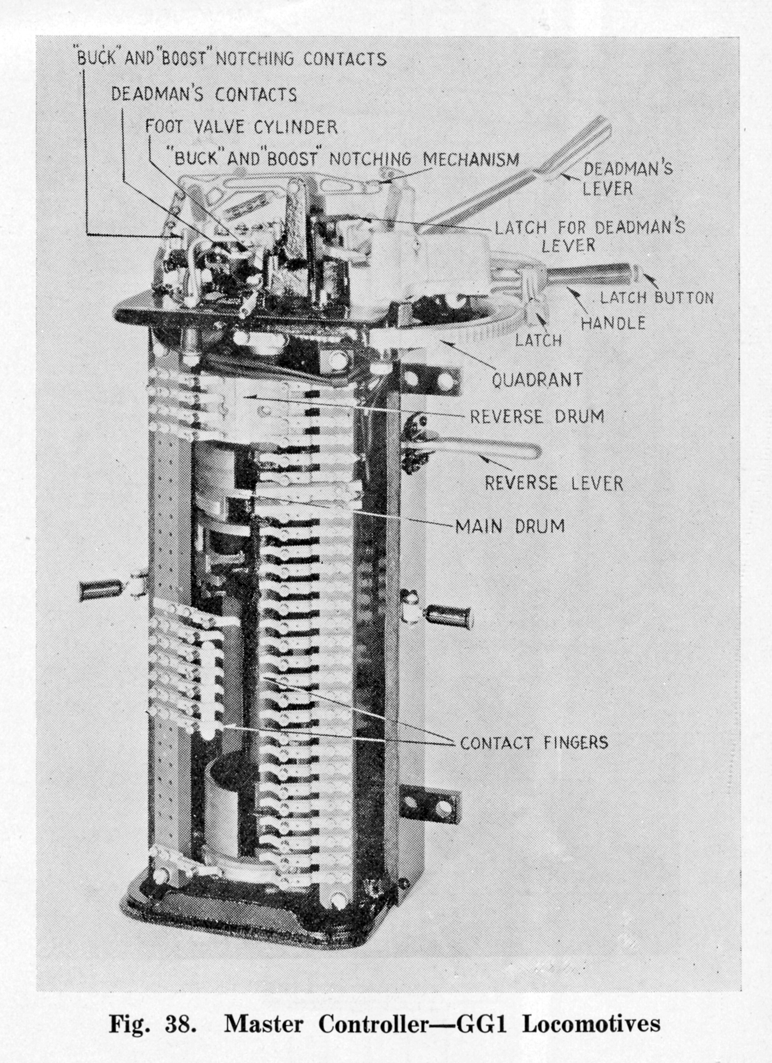 PRR GG1 Master Controller by Edmund, on Flickr
Regards, Ed
3 Likes
I’ve occasionally had folks comment on my running models of various ‘motors’ on my layout which doesn’t have third rail or catenary modeled. I simply refer them to this photo:
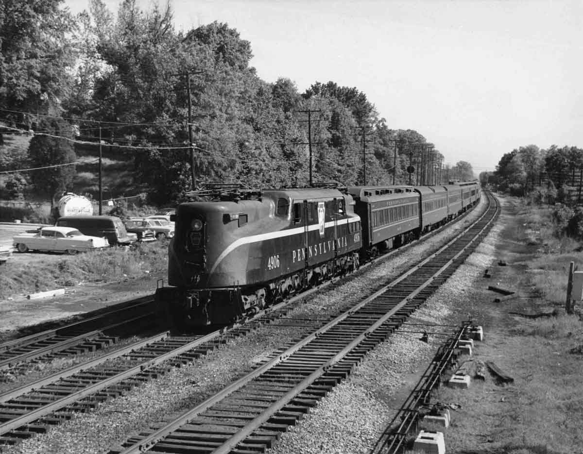
Classic Trains Photo of the Day
Battery power? Coasting down grade so no pans needed? GG1 converted to diesel?
On May 28, 1964, at Alexandria Junction, Md., Pennsylvania Railroad GG1 electric 4906 brings up the rear of Washington–New York train 126, which diesels are towing backward over the Baltimore & Ohio owing to a derailment on the PRR at Lanham, Md.
Ara Mesrobian photo
Cheers, Ed
4 Likes
You know, if there were a third rail in between the outer two that would definitely explain where that G’s getting it’s power!
2 Likes
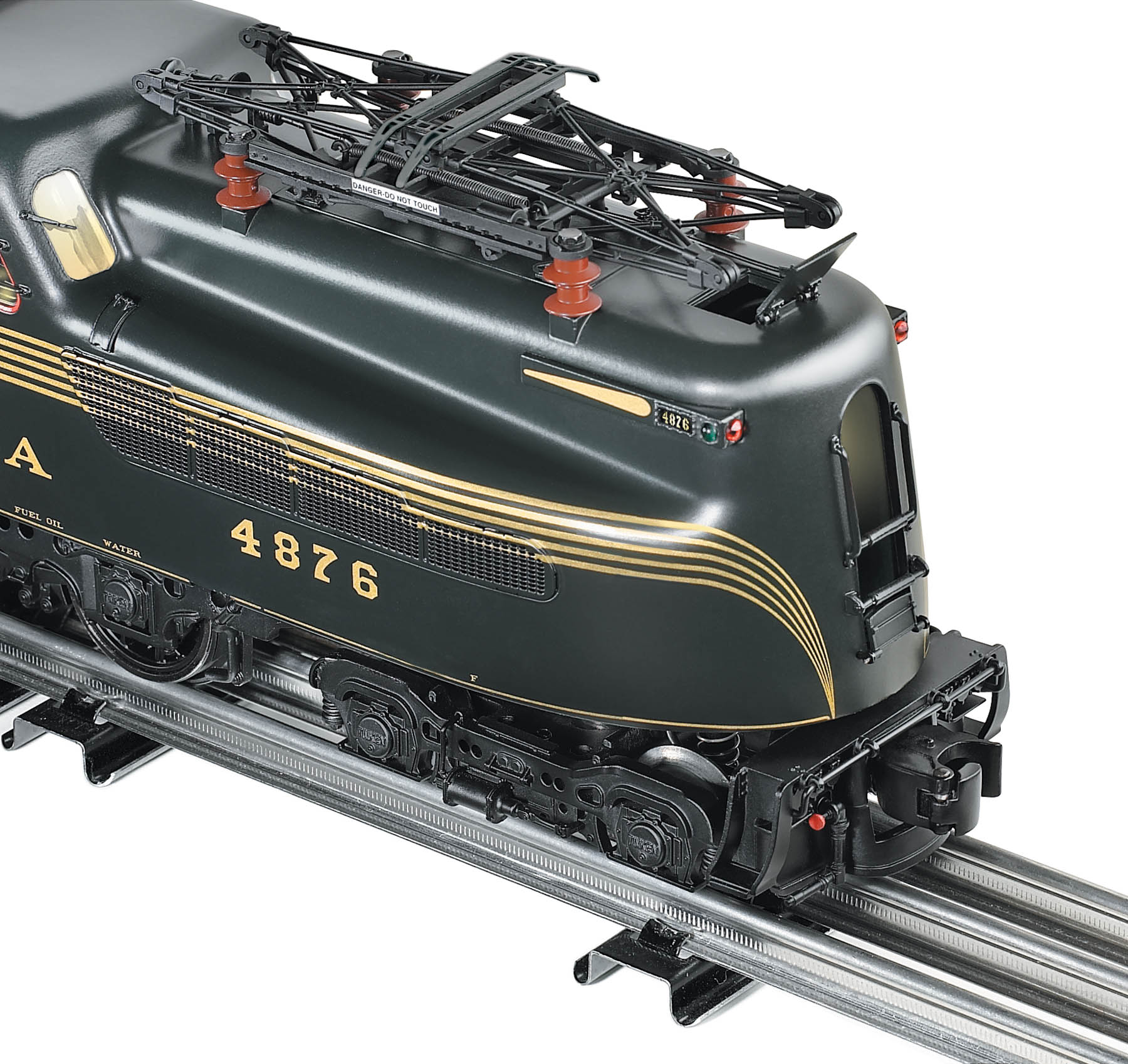
I have a perfectly 2-rail O-scale G that happily runs pans-down…
4 Likes
As it should! ![]()
1 Like