thanks for joining my conversation guys however does anyone have a detailed picture of the cab from the manual showing all the controls labelled like headlights,the dual pantograph double pole double throw knife switches and when the controls were modified from two to one knife switch for pantographs and the picture of the bell and wiper valves apart from the one that was released in the 2009 summer trains magazine probably in preserved GG1 locomotives and does anyone have a clear picture of this diagram il_fullxfull.1168538774_7hd4.jpg (1500×854) pls reply below
regards,
e44viv
I’d also like to know whether new haven electrics ep1,ep2,ep3,ef1,ef2,ef3 used transformer taps with universal motors under ac and rheostats under dc catenary.
Not exactly an ‘off-the-shelf’ part:
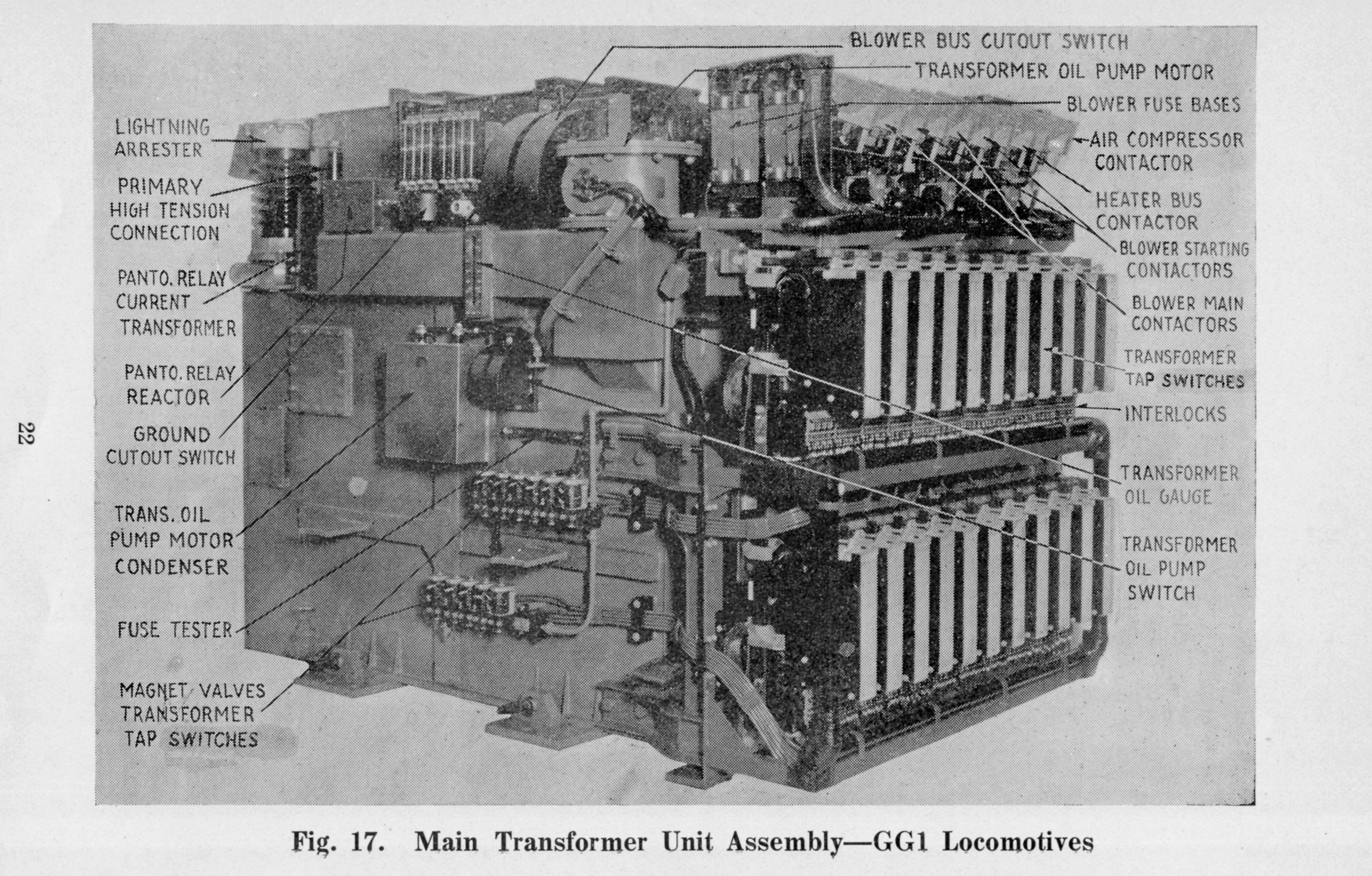 PRR GG1 Main Transformer_0009 by Edmund, on Flickr
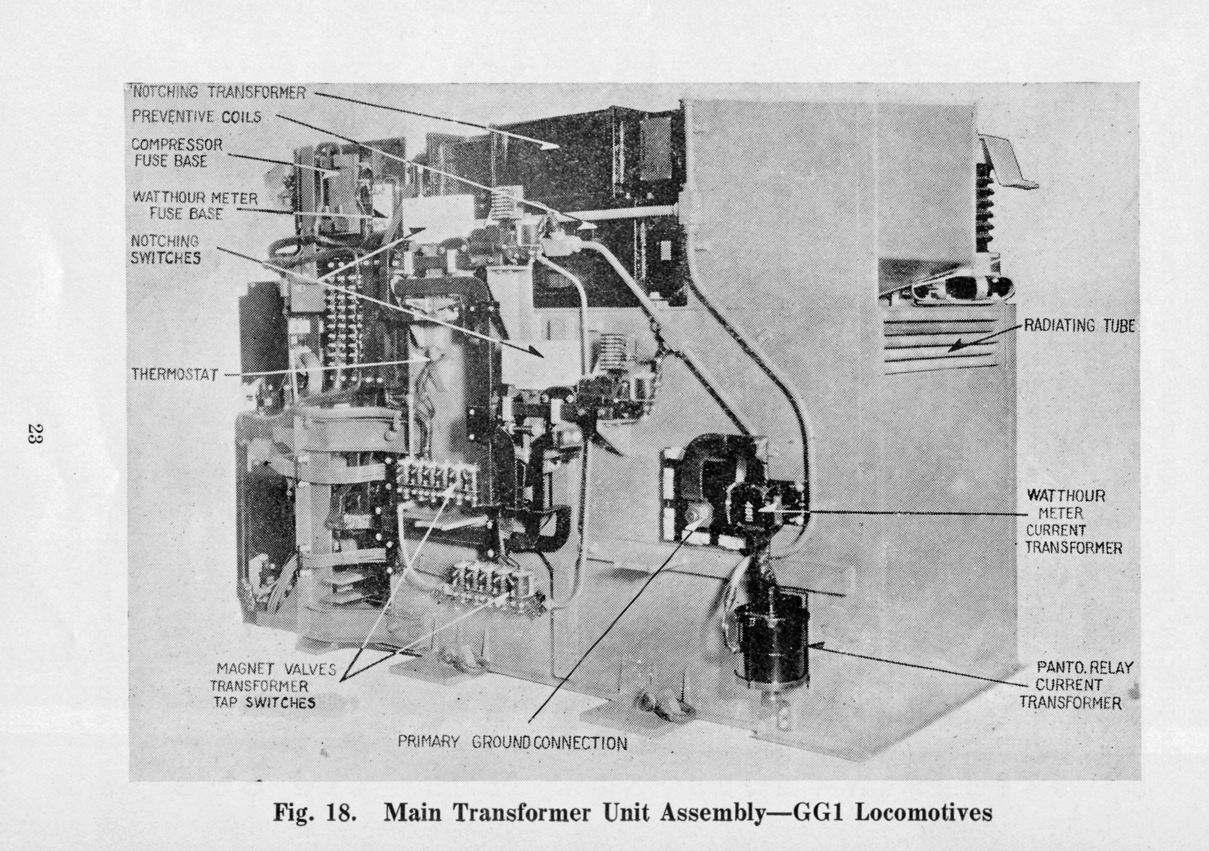 PRR GG1 Main Transformer by Edmund, on Flickr
Now where did I put the keys to my time machine?
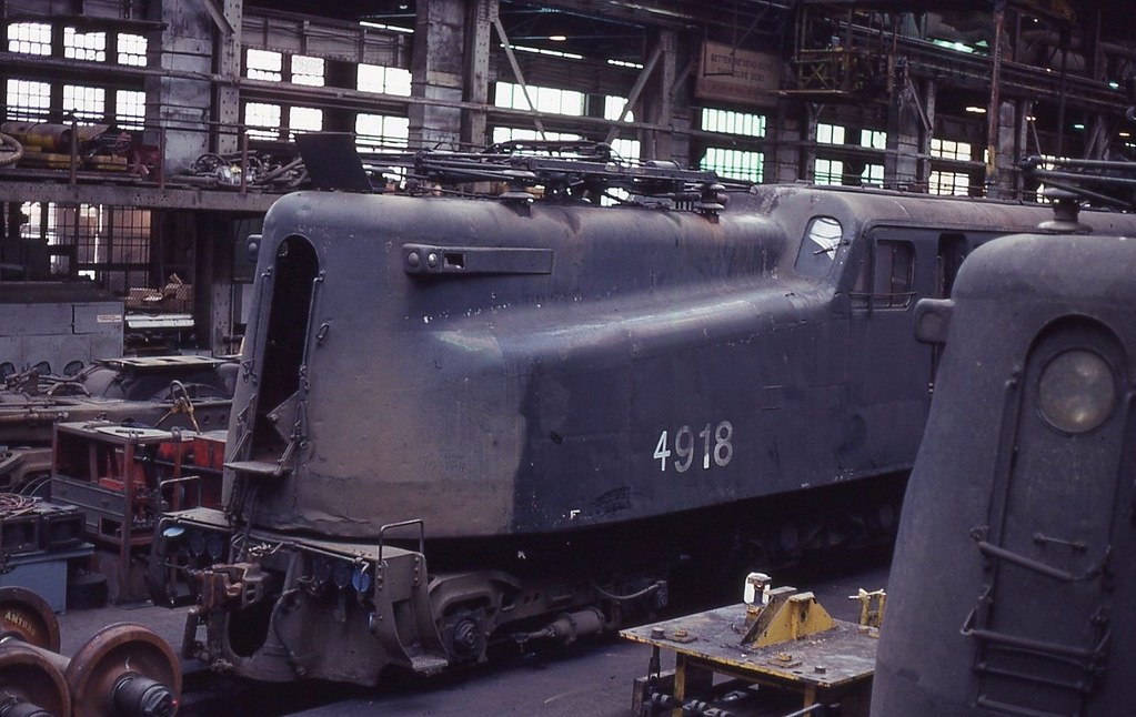 CONRAIL GG1 4918 Wilmington shop by Charles Warren, on Flickr
Here’s a rare shot showing the ladder to the roof access hatch with the grounding lever next to it. Note lockout pin hanging from chain.
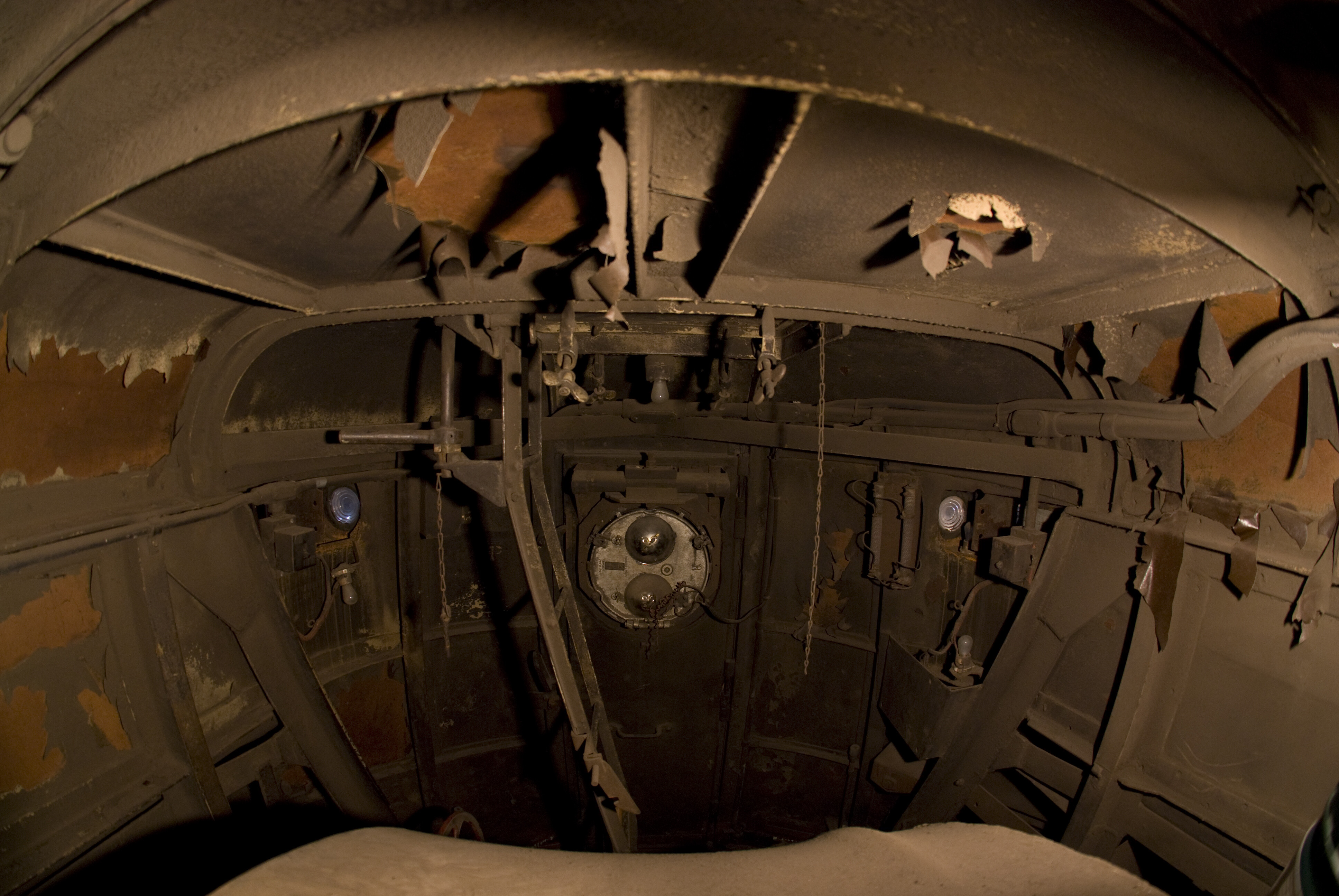 Interior Nose Fisheye by David Fullarton, on Flickr
Good Luck, Ed
3 Likes
Perhaps you could contact Firecrown to see if they could repost this image at a readable resolution?
As it stands it is worthless. If anyone knows if it appeared in any Classic Trains issue I’d like to know as I have nearly every issue. It did not appear in the Summer 2009 issue.
Side note: I was curious about why the GG1s I saw photographed at the Philadelphia Army-Navy games always seemed to have both pans up. The answers I got was because the Stadium yard had ‘high wire’ and double pans were called for any time that condition existed. Signs were placed for the engineers thus:
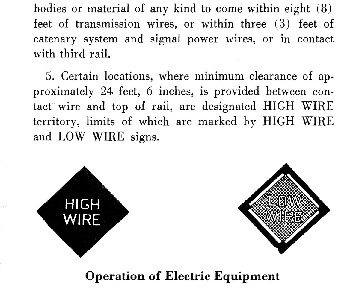 PRR_CT-290 High Low Wire by Edmund, on Flickr
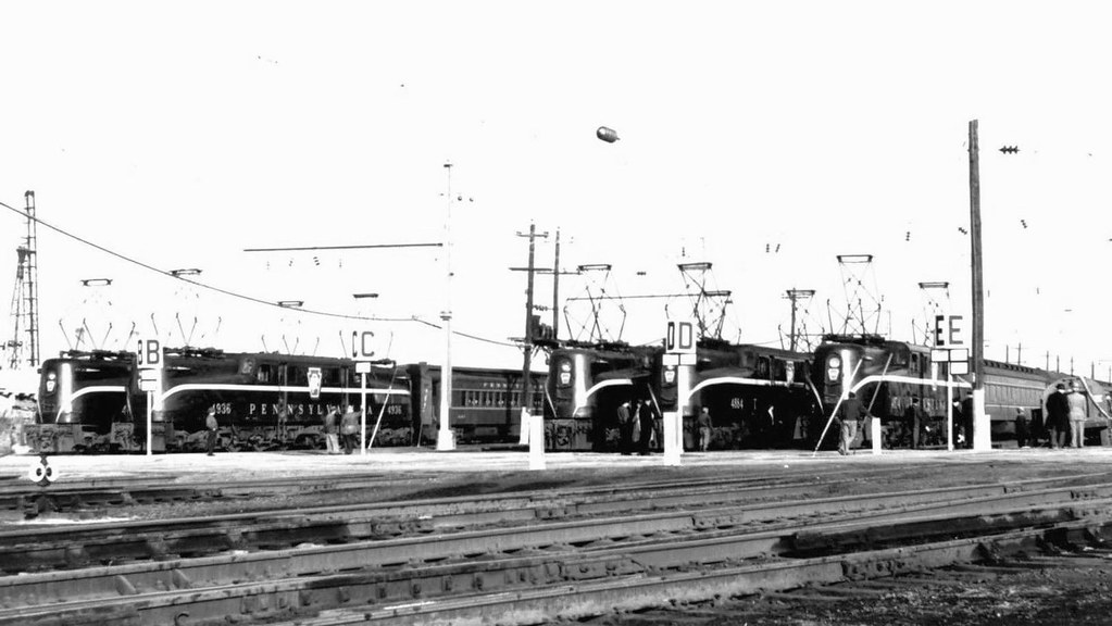 PRR GG1 SPECIALS at the ARMY NAVY game by Charles Warren, on Flickr
Or, as I previously mentioned, in icing conditions:
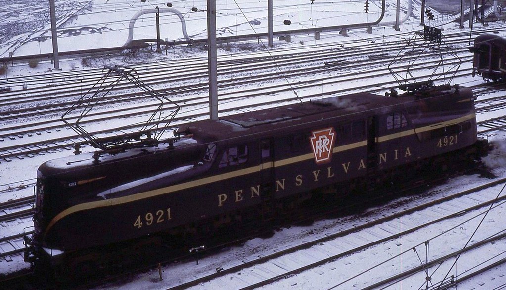 PRR GG1 4921 by Charles Warren, on Flickr
The Railroad Museum of Pennsylvania has a neat 360° view of a GG1 cab but unfortunately everything is plastered in gray paint!
https://www.rrmuseumpa.org/QR/gg1/
Good Luck, Ed
2 Likes
Maybe you can tell something from what’s left in these pictures:
2 Likes
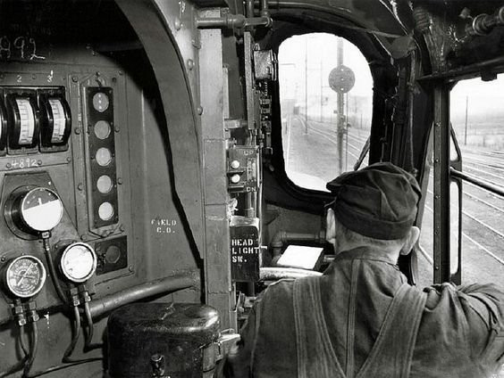
thanks a bunch, by the way can anyone tell me where are the knife switches for selecting the pantographs and also there is a valve as gmpullman had mentioned previously sitting ahead of the independent brake valve used for ringing the bell and there is another valve above it next to the window to the right could this have been for wipers and for headlights where would the controls have been and sanders and if gmpullman has anymore incab photos of GG1s showing the controls labelled request him to provide that too.
regards,
e44viv
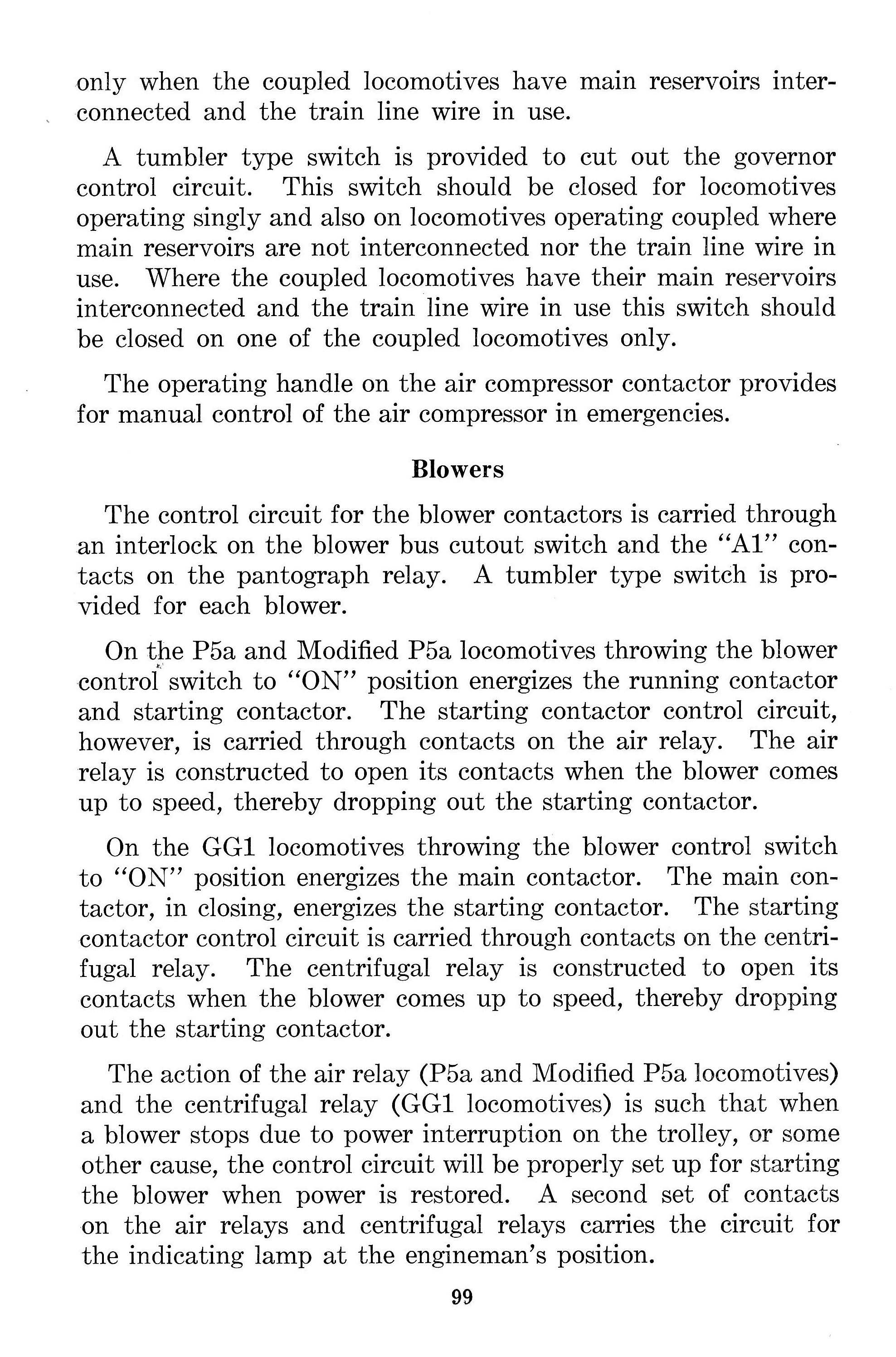
If anyone is still following along, I scanned four pages of text that explains the pantograph operation:
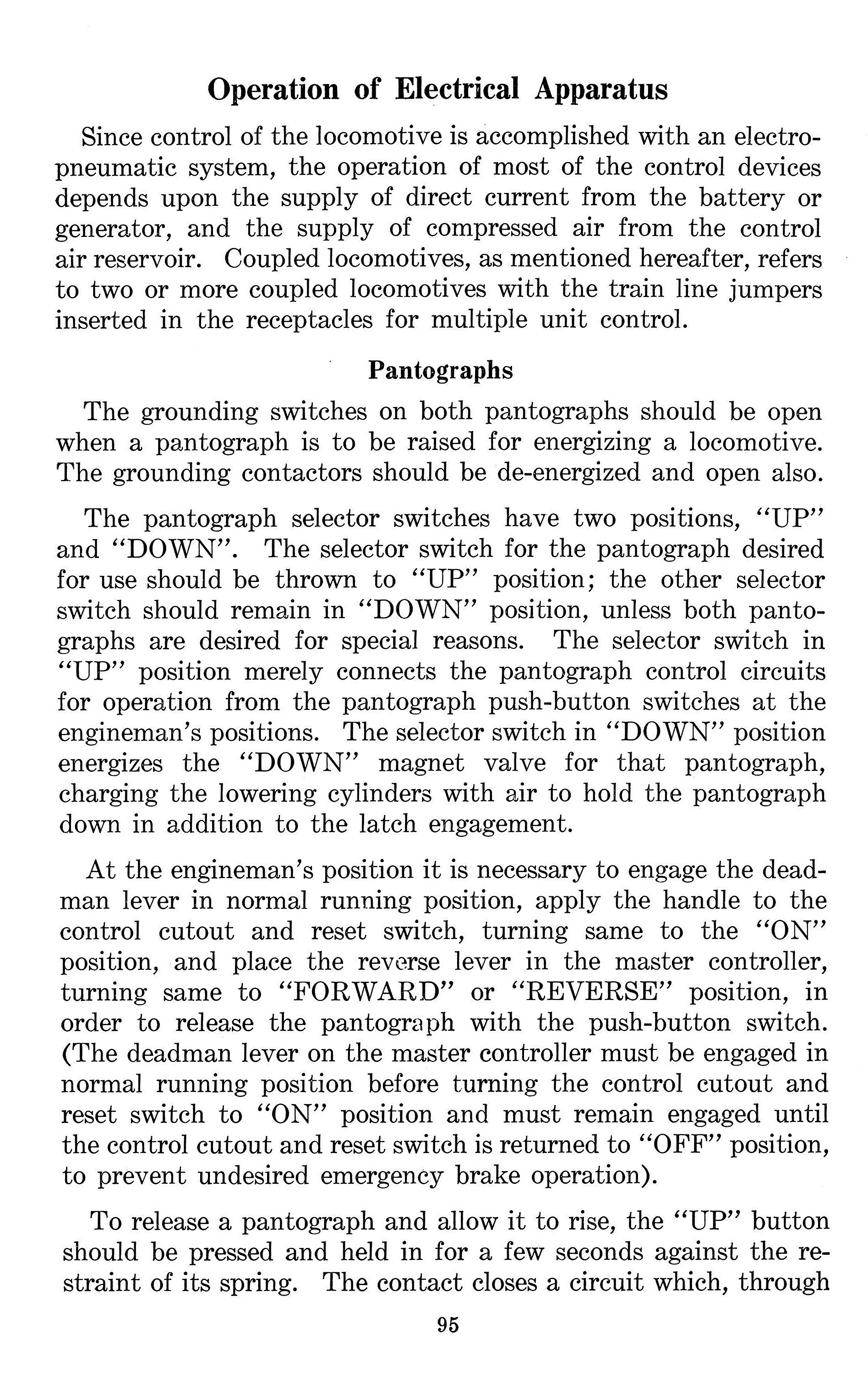 PRR GG1 Pantograph Text 95 by Edmund, on Flickr
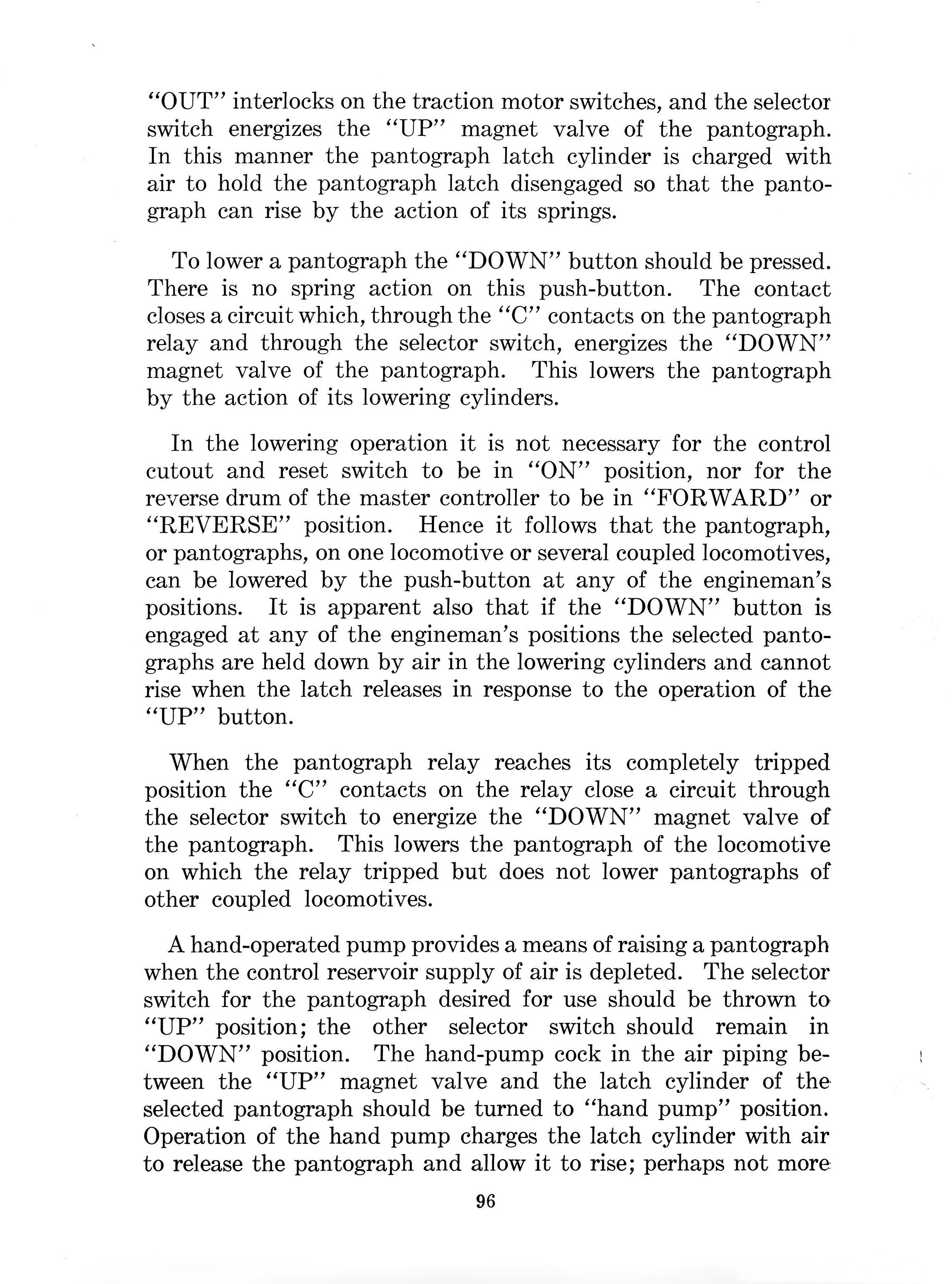 PRR GG1 Pantograph 96 by Edmund, on Flickr
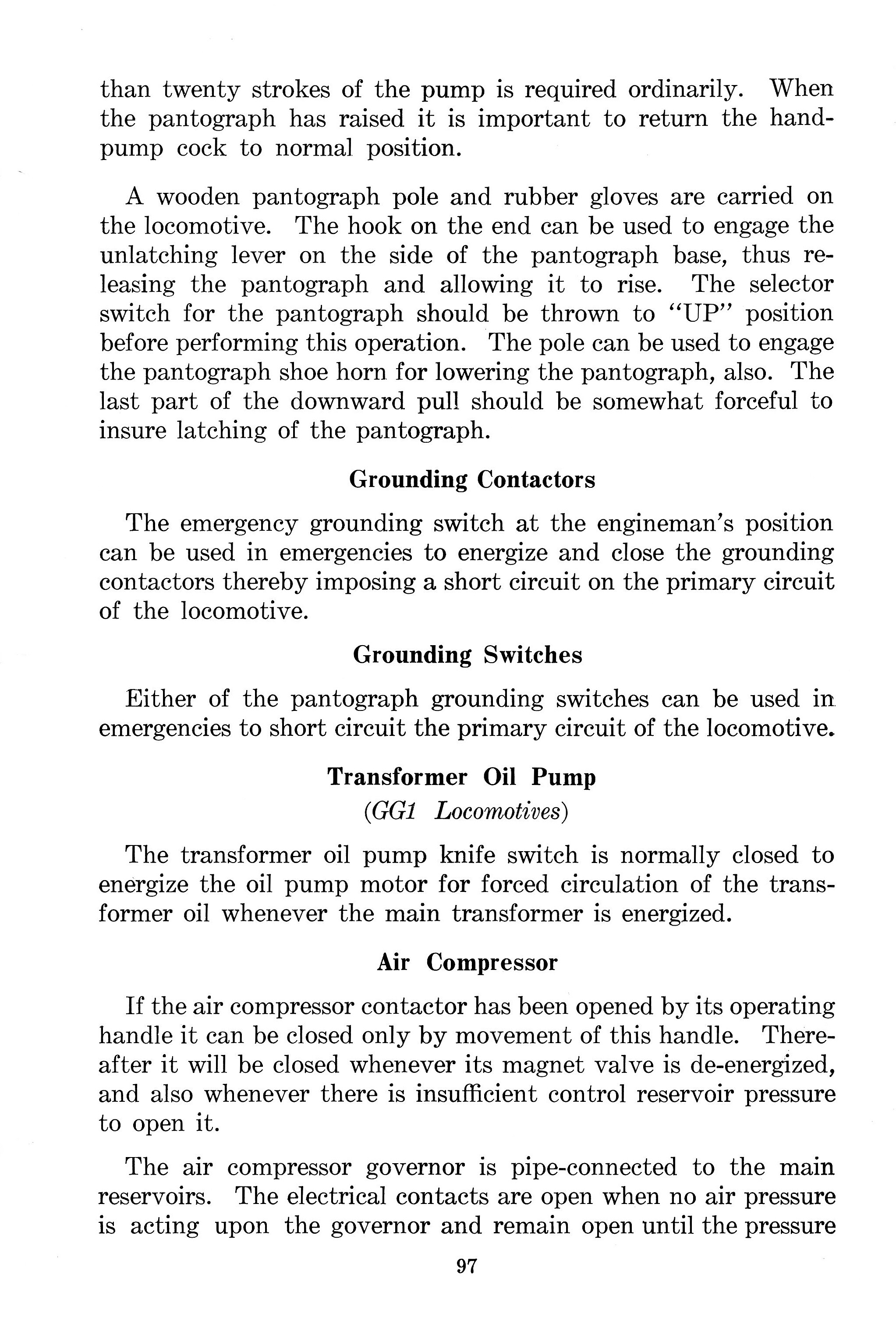 PRR GG1 Pantograph Text 97 by Edmund, on Flickr
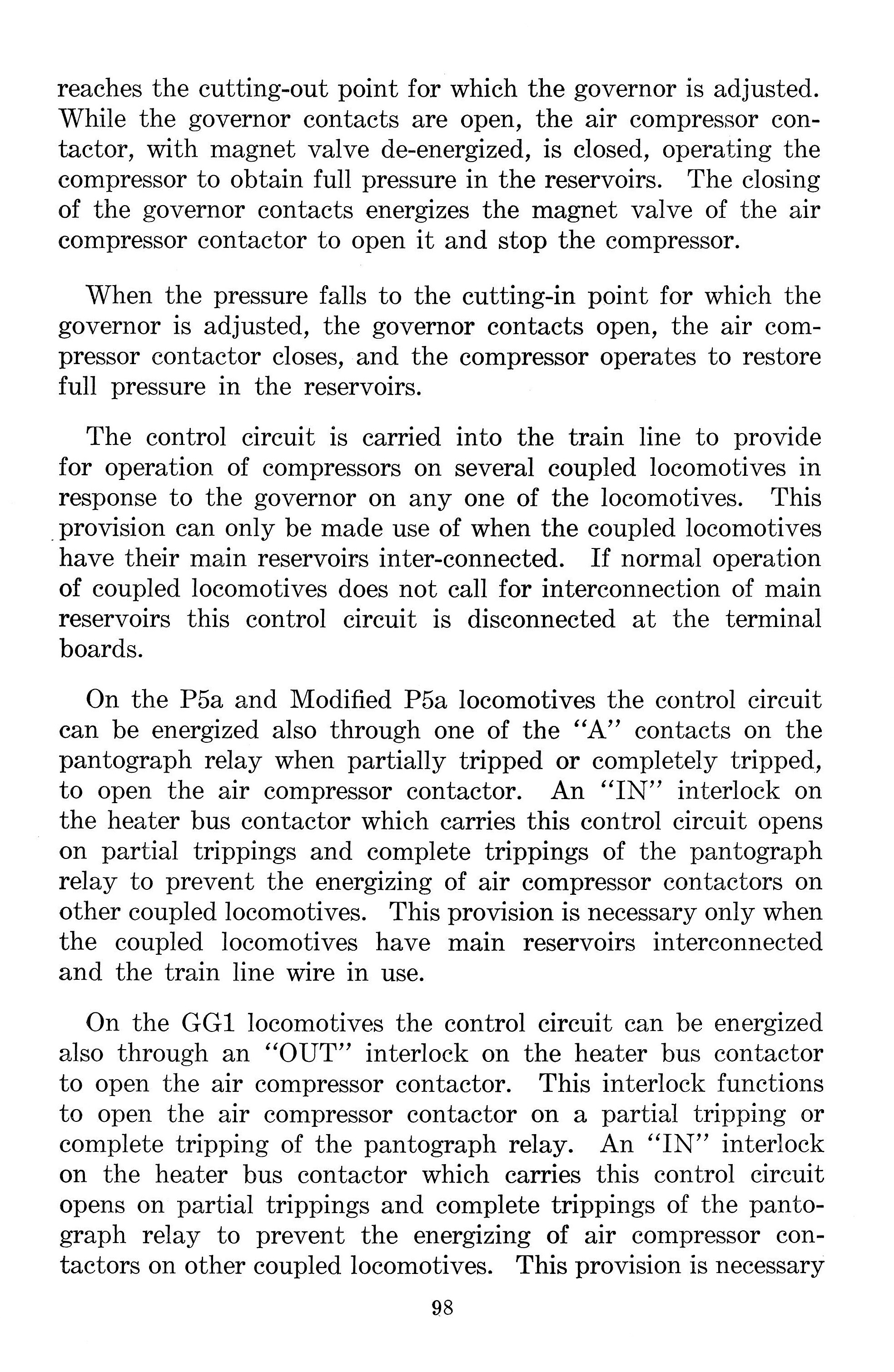 PRR GG1 Pantograph Text 98 by Edmund, on Flickr
I’ll add the paragraph or two from page 99 later today.
All the recent photos show the modified knife switch. From what I can surmise, the wiring modification required the engineer to be at the cab of the end that he wanted the pantograph to be raised. If both pantographs were to be raised he would have to pass through to the other cab. Perhaps the original wiring didn’t fulfill the requirements or was simply too costly to maintain.
This photo shows the ‘simplified’ knife switch:
 IMG00014-20100626-1448 by David Fullarton, on Flickr
Note the raise and lower pushbuttons were tactile with a convex surface on ‘Raise’ and flat or convex on ‘Lower’.
I dislike the forum software that formats images to unreadable sizes. Click the image to go to Flickr where it can be enlarged and/or downloaded.
Regards, Ed
1 Like
I can’t thank you enough gmpullman for sharing this crucial piece of evidence,by the way could you also tell me whether the valve ahead of the brake valve below the front window was for the bell and how many times it had to be turned for operating the bell and the other valve which is partially visible in the above photo to the extreme right at a higher level controlled windscreen wipers and where the controls for headlights would have been along with sanders and when the modification of knife switches were carried out for pantograph control and whether the controls including those for pantograph and layout were similar on prr p5,p5a,dd2,O1 which were prototypes of gg1s and kindly upload page 99 too.
thanks
e44viv
I’m surprised the bell valve is a globe valve. I’d have expected something like a quarter-turn cock that would have an inherently good seal when closed. That might also give easier transition to full airflow if that would help with the ‘dull and muddy’ ringer action.
Incidentally the link to the whole 37 (at present) scanned pages of the manual is

1 Like
Thanks,do you have any pages in the manual that explains the location of headlights,cab lights,class lights and valves for wiper operation as seen in the above cab image above the bell valve which is situated ahead of the independent brake valve but visible partially and does the manual consist only of 37 pages or any more pages are present.And whether the cab controls for pantographs,bells,throttle,reverser,dead man pedal was comparable across prr p5s,p5a,dd2 and O1 which were based on the GG1.
I’m still looking into that! I have some inkling that the bell was operated through a ‘magnet valve’ and therefore the bell would be an electric switch. It appears there’s also a bell operating switch for the fireman (helper as noted in the operating manual).
Also, I believe the sanders were operated through a magnet valve and was actuated by a foot switch. Left foot on the deadman, right foot free for the sanders?
The P5as used a magnet valve for the whistle valve. I’d like to hear some first-hand testimony on the operation of the grounding switch. Particularly the manual grounding switch. 11,000 volts AC 25 cycle to ground?
e44viv is asking questions at a staccato rate. Then adding the New Haven motors in there as well? More than I can handle.
The manual consists of approximately 300 pages. I don’t have a staff on hand to scan, orient, crop, sharpen and remove scratches and blemishes from each page only to post them here for your enlightenment. Someone has to feed the cats.
What I initially thought was the bell valve may well be what the engine crew had for ‘defrosters’! Study the cab photos and you’ll see a duct coming off the tops of the resistance heaters and the globe valve seems to control the flow of an airstream toward the windshield.
Good thing they had cab signals!
Regards, Ed
Ok,I get it at least you have got so many pages covering important aspects relating to operation of GG1 locomotives that is more than adequate.I sincerelely apologise for putting questions at a lightning fast rate as I am really curious to learn about these locomotives and new haven ones as I am a researcher and a railway enthusiast,by the way would you be knowing whether p5,p5a locomotives from prr had same controls like GG1s as the one preserved number 4702 doesn’t have any in cab photos.
regards
e44viv
More probably one hand on the 45-degree lever to allow either foot to work the sanders. PRR was sensible enough to recognize that ‘pedal only’ wasn’t a good enough solution, analogy with truck operation notwithstanding.
The ‘alerter’ or ‘vigilance control’ systems that came later are better thought out than a system requiring continuous haptic actuation.
1 Like
My understanding was that the ringer used pneumatic power, but was electromagnetically actuated (cf. stops in an organ). The valve or cock would only be opened to provide ‘motive power’ to move the clapper; actuation would be via (very probably) a draw-knob arrangement that you would pull to electrically start the ringing, and then slap in when done. It would be ambiguous to have a toggling button, and more expensive to have a two-button switch for ‘on’ and ‘off’ that might be confused with (say) the panto controls.
The arrangement would have to ensure the bell would ring continuously if any control were actuated, without supplying too much ‘electricity’ to the magnet valve if more than one control were actuated. It would also NOT be like a whistle cord that had to be continually pulled to keep the sound on.
2 Likes
The remaining P5 is #4700, and the only solution that will satisfy your particular zeal is going to involve being granted researcher’s access to the cab of the locomotive and a trip to St. Louis to see and photograph to your satisfaction.
I have no idea what their procedure on scholarly access is, but I would NOT hit them with a long breathless run-on sentence that expects them to find and document all the answers for free.
2 Likes
thanks for the information.does anyone know where the controls for GG1 for operating the headlights,cab lights and other lighting were located.
I’ll let you guess as to the headlight:
I find that there is a great deal of variation among the ‘members’ of the GG1 fleet. Note the duplex air brake gauges arranged in a triangular fashion. Other G’s had four gauges in a row.
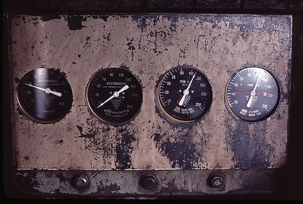 GG1 #4881: Brake Gauges by Steve Baldwin, on Flickr
Auxiliary lighting was switched using four circuit breakers (maybe they were simply switches) to the far left of the engineer, just above the air gauges and below the speed indicator:
 Cab Fisheye by David Fullarton, on Flickr
From left: Hood; Aisle; Cab; Gauge. There was also a single lamp over each of the engineer and fireman’s seat for reading train orders.
Good Luck, Ed
2 Likes
thanks for letting me do the guessing work.I absolutely appreciate it when someone throws a challenge to me.According to my analysis and after seeing photos of gg1 cabs I can say for sure that there were a set of 4 switches behind the engineer’s controls and they should have controlled the class lights,headlights,cab lights,etc.And are you sure that GG1s with that lukenheimer like steam whistles operated on air would have sounded somewhere closer to hancock 4700 air whistles as they emulated steam whistles.
He was being humorous about the headlight switch; it is clearly stenciled as such, ahead of the engineer, in his picture (with the ‘sw’ for ‘switch’ abbreviated).
I would expect the whistle to sound like a standard PRR passenger whistle blown on main reservoir air.
2 Likes