I’m not ‘sure’ about what anything sounded like some 90 years ago. The GG1 used for writing up the operators manual along with the ‘official’ PRR photographs taken at delivery show a cylindrical air whislte. As Woke mentions it certainly may have been the standard passenger steam whistle. It MAY have been modified to operate more efficiently on air rather than steam.
By the time the ‘production run’ of GG1s were delivered they all had Leslie Typhon A-200-156 diaphragm horns applied and these remained in place for their remaining years.
I truly appreciate it for sharing this piece of information,however do you reckon that the cylindrical whistle found on GG1s resembled a lukenheimer design probably 3 chime as it occured and to me and of all the photos I have seen of steam whistles lukenheimer ones bear the closest resemblance in terms of chambers,bell design,etc.
regards
References I see have the PRR passenger whistle (E-G-B chord) made in their own shops. They might appear similar to a Lukenheimer design, but they are not products of that company.
Can you tell me whether any PRR steam whistles 3 chime bear any resemblance to the ones used on GG1s I mean the one that looks somewhat like a Lukenheimer design.And can you tell me whether 3 chime was the standard configuration to be used on early electric locomotives on air or were there 5chime,4chime,etc as well as on steam locomotives.Kindly throw some light on this topic.Also I would like to know whether Lukenheimer,Kinsley,Nathan manufactured air whistles for early electric locomotives during the steam era apart from crosby,GE/WABCO clarion and trombone whistles and new york central shop made crossby like 3 chime designs used on their electric locomotives like s motors,t motors,some on their alco switchers,etc.
Regards
Until proven otherwise, I’m presuming that the whistle on the original GG1s was a standard passenger 3-chime, perhaps taken from a pool of whistles serviced and waiting to be applied to steam locomotives. It would be relatively easy to find recordings of a PRR whistle blown on steam vs. at a ‘whistle blow’ on compressed air to get an idea of the sound.
One reference indicated that the standard PRR 3-chime whistle design went back to 1875; whistles are not in my range of historical interest so I can’t tell you what principles or historical examples were involved in its design or fabrication.
The early PRR electric equipment, to my knowledge, used plain air whistles – the ones on the MP54s as late as the early Seventies having a kind of blowing-into-a-bottle sound to them. I do not know if these were used on the ‘rats’ or the ‘mainline’ electrics like the O and P classes – the surviving unit at St.Louis might or might not have physical evidence; you’d be better off looking at blueprints. Certainly air horns were fitted to any electrics operating on the main line by the late Thirties.
I don’t know offhand of any electric locomotive that had more than 3 chimes on air; it would be counterproductive in terms of air mass flow for not much benefit as an alert device. Diaphragm horns, of course, were much more efficient.
Thanks a bunch for sharing this insightful information, can you tell me whether the whistles seen on PRR FF1, AA1 were of Crosby or not as photos show them looking exactly like Crosbys and did PRR DD1s use Kinsley whistles or whistles made at their shops bearing some resemblance to Kinsley’s designs what’s your take on this hit me, can anyone give an idea where I can find a PRR passenger whistle blown on air vs steam to get an idea.
Thanks
regards
e44viv
Your first stop should be the Railroad Museum of Pennsylvania library – they have an online search tool, and you can back that up by consulting the Archivist with specific technical requests outside the finding aid.
A reminder that restoring a GG-1 to actual service is not impossible, although very expensive and not by anymeans as originally powered and controled.
The original motors would be operated as dc motors, perhaps overhauled with modern insulation and removal of coils needed for efficient 25Hz ac operation, but not needed for efficient dc operation. It would use the same rectifiers and control equipment as existing ac-rectifier-dc-chopper-control locomotives, or those recently retired, or commercial portable power equipment. Ditto transformers if piossible. It would be configured for both 25,000 and 1q2,500 volts for primary use in the NEC, but the dc “power-rail” might be 1500 volts for guest appearances for dc operation in the Chicago area. It shouldchavea consist of Congressional-Senator Budds, with restored interiors or rebuilt P70 picture-window arch-roofs with the original PRR gold (yellow?) stripes on theTuascan-red. I can dream can’t I?
I would still prefer replacing the DC twin motors with new and better ones. In 1978 that involved welded fabrication with some lost-foam castings; now much of the construction could be 3D-printed with the same equipment SpaceX is using for its rocket motors.
All the switchgear would be prototypes for hybrid dual-mode lite; the transversion made from any potential catenary voltage and frequency to 1200 or 1500V DC-Link and then synthesized AC to the traction motors, with control as already costed-down for AC diesel-electrics. Note that existing switchgear for early AC locomotives is already nearly capable of the GG1’s continuous hp rating as a whole locomotive, whereas a rebuilt locomotive might have only a few axles actually driven.
No real objection to making it into a modern AC-motored locomotive, I’d still power all six axles and enjoy the additional hauling piower for 20-car excursion trains. Otherwise, using the original motors on dc is a nod to preservationism in general.
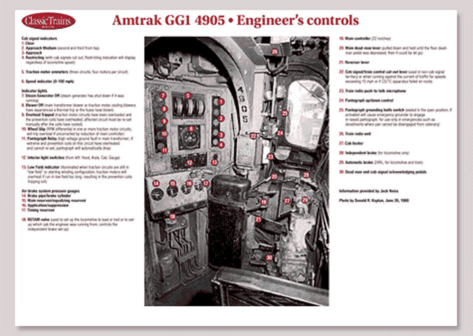
I can’t thank you all enough for responding and participating actively to my post, what I can make out is GG1s used single phase ac motors with tap changer a technology used by Germany, Austria, Swiss railways since 1920s and for that diagram from trains magazine showing cab controls could anyone discern where the bell ringer knob should have been as gmpullman told me it was some distinct knob but I can’t locate it in the cab.
Thanks
cheers
e44viv
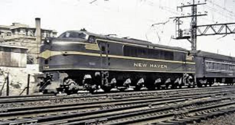
I would not call the GG-1 motors single-phace ac motors, because the were close in design to those in use on New Haven 4-6-6-4 (2-C-C-2) electrics, both the box cabs and the streamlined, and only slightly different than earlier 2-6-2+2-6-2 (1-C-1+1-C-1) box cabs. These ran perfectly well on DC into Grand Central Terminal. They had brushes and commutators, while AC motors normally used slip rings and were either single-frequency induction motors or non-synchronous with slanted armeture bars. On the New Haven, the dc control system was separate from the tap-changing ac control system and used conventional dc resistance-and-transition control. The NewcHaven also used similar commutator motors on the last series of 4-6-6-4s that ran to Bay Ridge with freight and Penn Station with passengers and did not have the dc controls and third-rail pick-up.
He did not tell you it was a ‘knob’, and in June of last year he pointed you to a 360-degree image at the RRMPA that shows the bell cutout cock, just ahead of the independent brake as he said…
Thanks for pointing that out probably I had that wrong the universal motors that could run on ac and dc power were used on gg1 locomotives not single phase ac motors, now coming to that cock for a long time I have been thinking what it was for what purpose it served and all I could discern was probably it used to control window wipers or a slight hint it was a bell cock now is it apparent after reading through woke’s post today that I was 100% right. Coming to my next point I know two buttons were there to control the pantographs probably one for each pantograph but gmpullman indicated there was a selector switch for selecting pantographs in one of the cabs later removed so each panto above that cab had to be raised only by entering example cab2 pantograph by entering that cab and cab1 pantograph by entering that cab and what intrigues me givent that it is a majestic and fantastic locomotive is that was there anything like individual pantograph cut off cocks,valves and a hand pump to raise them when no air was available while starting and if the selection switch applied in this scenario and you could select which panto was up how did this work can someone throw some light on this.
thanks
e44viv
You’re not really ‘wrong’; the GG1s ran their whole lives on single-phase AC power, so in a sense those universal motors were acting as single-phase motors. Use the phrase ‘motors running on single-phase 25-cycle AC’ (which grammatically is almost the same thing) and you’ll be fine.
I believe the 428A twin motors as used in the DD2 (and prospective GG2s and large helper/snapper locomotives proposed for the 1943 electrification plan west of Harrisburg) were intended and designed only to run on AC.
The pantographs were sprung to accommodate the range from extreme low wire (as in the North River tunnels) up to high wire as illustrated in one of Ed’s posts in this thread. Obviously those springs would be at their greatest compression with the pans all the way down and locked, so no air would be needed to lift the pans to the wire. Instead, the latching mechanism was released with a small air cylinder, and this is what the hand pump developed pressure to release (with the air compressors coming on and building main-reservoir and control air pressure once the pan was on the wire, after which the air for lowering a pan again would be available).
Thanks a ton for reassuring me about the motors and elaborating about the pantographs now, where was the pump for pantographs located and whether in any of the preserved units or through any archives you can at least indicate where it should have been and whether when you used it to raise the panto by default it raised both the pantos or you could select which one to raise and if yes where was that selection switch located and did those two buttons marked as panto graph buttons were for both pantos or there is something else to it kindly illuminate this for me.
thanks
cheers
e44viv
e44viv
Did we ever get Angela to provide a clear and legible image of the controls of locomotive 4905 from the ‘special issue’, posted April 24 2009?
Ed will have the relevant information in his copy of the locomotive operating instructions; he has posted about it on the forums several times. In a pinch there’s an accessible manual at the Railroad Museum of Pennsylvania:
Pennsylvania Historical and Museum Commission (PHMC) (Non-Circulating) C-P4- TF 975 .W45 O6 1951
These controls would figure prominently in any accurate train-simulator G. I have not found the corresponding documentation or any screenshots that would be helpful, but contacting a simulator community might rapidly produce results – how good they would prove to actually be, I can’t say.