Philosophy Friday -- How did you develop your track plan?

In light of getting the weekend off (no forums whilst the site is down), I’m going to pose an easy question today… no books, no tomes, no icky “feelings”… [:P]

How did you develop your track plan?

Which came first? The track? The town? The terrain? Did you plan it? (Really…??) Or did your track plan just sorta “happen”, as you went along… If you had it to do all over again, knowing what you know now, what would you change? (And WHY?) What do you especially LIKE about your track plan? What do you absolutely HATE? (And WHY?)

Oops!

(It wasn’t me… [:-^])

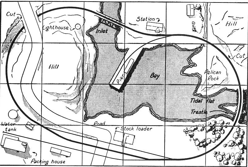
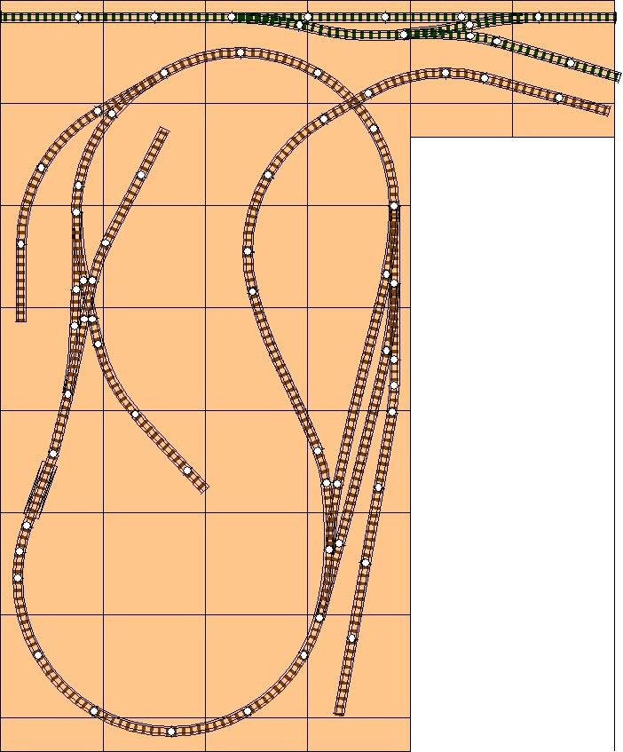
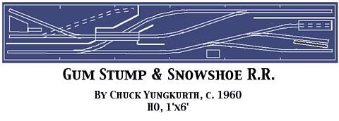
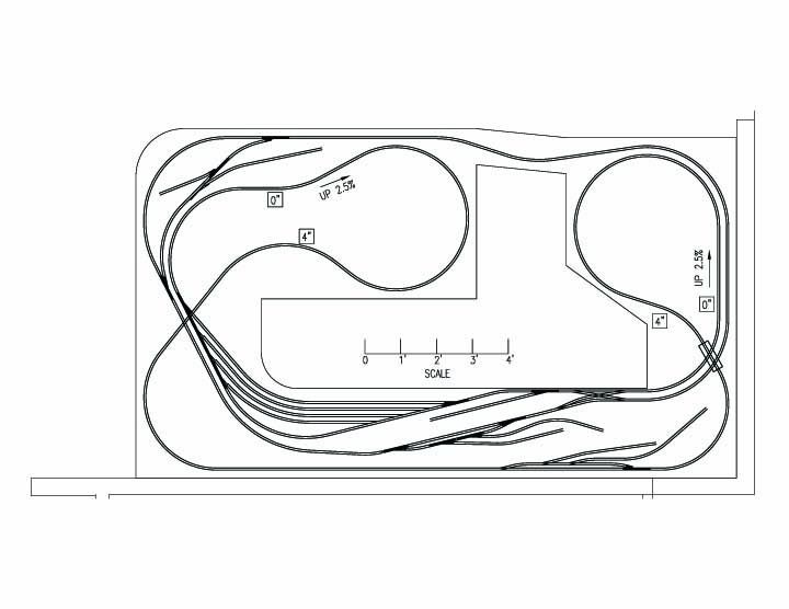
Feel free to post pictures of your track plan-- I’d enjoy seeing it!

Do you have a single deck? A double-deck? Triple-deck? (How do you manage that, btw-- doesn’t that strain your neck just a tad??)

(Oh, and be sure to include a quick overview of the purpose behind your railroad, if you have one, to help us interpret your plan.)

As always, I look forward to hearing your thoughts and opinions!

Thank you everybody, very much, for making these Philosophy Friday posts so much fun!!!

John

This’ll have to be real quick…one hour left before lights-out!

First, I knew what I wanted in the way of function and form for my tracks and bench respectively.

Then I mapped it out on 1/4" graph paper, the large stuff measuring 14" X 18" or so. I scaled out large curves with clearances, long turnouts, and made sure I had the yard I had learned to include (which my first effort did not).

I also wanted some good elevations, so a folded loop seemed to be in the offing…no multiple decks for this kid.

The purpose, for me, was foremost to be able to enjoy watching my steamers on the move with their valve gear and rods in motion. That meant I had to be the center of the universe for them gals, and it logically meant I had to centralize operations in a pit, since I was being shoved into a corner of the basement. No regrets, although having to duck under is no picnic. Still able to do it easily…it’s just a pain in the back too literally when I scape the skin off it.

-Crandell

Yeah, I figured I’d try to squeak it in there and hope that some peeps could see it before the line went silent… how did we all cope before the Internet anyway? I have distant memories of having to go places and do things and actually interact with real people and everything…

UGH!!!

… it was awful!

Maybe it was all just a dream…

You have some very broad and beautiful curves on your layout-- great for rail-fanning.

Have you ever tried crashing them together like on the Adam’s Family???

(blinks eyes innocently and then high-tails it for the hills!!! [:P] )

[(-D] [:D] [(-D] [:D] [(-D] [:D]

John

For me, the prototype has always come first.

I spent a considerable amount of time actually walking the line and drawing the exact track plan of my 1:1 inspiration. In the process I learned exactly how (and to some extent, why) trains were operated as they were.

Granted that my layout doesn’t have a single station that has EXACTLY the track plan of its prototype equivalent. All of them were compromised, but the intent was (and is) to duplicate, as nearly as possible, the operation of the prototype.

The Tomikawa Tani Tetsudo portion of my layout is, “Protolanced,” but the timetable is that of an existing JNR branch and the station plans for the two intermediate stations are based solidly on prototypes I have seen and sketched.

That didn’t start when I decided to model the Upper Kiso Valley. I remember, as a schoolkid, trying to figure out how to build a reasonably accurate model of the Third Avenue “L” in the south Bronx. That was a couple of decades before I decided on my final prototype.

Chuck (Modeling Central Japan in September, 1964)

I started by downloading a copy of Atlas RTS and learning to use it a bit. Then I drew a 4x8, for a start, and quickly expanded it to a 4x12. I knew I had part of the family room to work with, but I didn’t know how much, so I didn’t want to press my luck. I also didn’t want to start a project that would be discouragingly large.

I put down some track, a continuous loop, mostly around the perimeter, with a crossover, yard and roundhouse. I realized that 4 feet was just too narrow, and I didn’t want to be confined to the perimeter just to make 18-inch curves. So, I went out to 5x12, which became the size of the layout I eventually built.

I also provided for expansion with a number of sidings around the edge which could be turned into connecting tracks to new layout sections. Now that I’m building a new section, though, I realize that none of those would really have worked very well, so they have remained spurs while the new connecting tracks were carved out of the existing mains.

For more, well, it’s about the witching hour…

Well I am on about on my eight layout after over forty years in the hobby and I can tell you two things that get written in stone more every year:

  1. Use the biggest radius you can fit in the area. My HO mainline will have nothing smaller than 48" radius and larger where possible.

  2. The prototype trackage is done for a reason. Study it, copy it and find drawings of the trackage you want to model and use it as close to what is on the paper as possible.

Both will lead to the maximum enjoyment.

In my case, a few realities dictated how the plan would evolve: the freelanced midwestern shortline theme was set, because that’s what interests me. Being a multi-use room, with household storage, mechanicals, and treadmill to share the room, two-foot deep shelf benchwork around 3.5 of the 4 walls had to be the footprint. With a 13x35 room and around the room shelving, there was ample space to develop a plan for a flat, midwestern shortline.

Those realities allowed me to not have to plan the exact trackplan in detail. A rough sketch was all that was needed initially. After laying the track loosely on the flat benchwork according to plan, I was able to adjust many finer points of the plan, like angles, curves, location of spurs, and angles of buildings (many buildings a building flats set at angles to provide some depth) by simply sliding the track around the benchwork. Seeing things in the flesh reveals some issues about a plan that even detailed drawings or programming software might not reveal.

After settling on a few certainties of the layout, I ran a bus wire and allowed for some blocking at the towns and got to the point where I was running trains. I’m still working on some of the finer adjustments to the angles of curves and buildings in some places. The parts that have been settled are now permanently affixed with roadbed and caulk, and even ballasted in some places. Other parts are still loose on the benchwork, just like a train set, waiting for my final assessment of the area.

This method won’t work for everyone. A theme with lots of vertical scenery elements tends to require open grid construction with risers, and experimenting with track arrangements isn’t possible after that type of benchwork has been built, so a mountainous themed layout might have to be more carefully planned up front. Again,

I took a sheet of blank paper, a black thin marker, and started drawing a line as track, turns, angles, overhead loops(dotted lines) until it seemed right, then added trestles, switches, sidings, next, stuck in where a town or village should be.

Thats all there was to it, now this is a logging operation with lots of leeway, stubby little engines so don’t worry about that turning radius foolishness, need a siding? bingo ! there it is, the same as a trestle or a lumber storage area.

I will keep is short and sweet. I new the railroad, CNW, I choose Madison, WI because a lot of the CNW track is still in use, making research easy. Madison just happens to be were I live BTW. Then I went to the good people on this forum for help and I needed a lot of it, thank you again Stein, Paul Jas and ODave amongst others. Here is the link:

http://cs.trains.com/trccs/forums/p/158171/1751078.aspx#1751078

As I started laying out the track plan, I realized what a waste of space that small “yard” is, so I plan on replacing it with another industry. I think I build a fiddle or actual yard off the layout once the main part is up and running.

Have a great weekend.

Sean

I went a different route that will probably make CNJ, Stein, and the other real model railroaders cringe.

I took some published small layout plans I really liked and tried to plan out how these might fit my proposed operating scheme. Some changes were made to link these together, and to better match my vision. The best of these ideas are in the planning hopper for “the” layout.

The layout consists of the Tidewater Central (Dec 1956 MR project layout), the Gum Stump & Snowshoe (April 1966 MR among others), and the Mower Lumber Co (Carl Arendt). An example of my process is starting with the Tidewater Central:

This is my second time building an adaptation of the Tidewater Central. On the harbor side, I have added a second spur and a “house track” behind the station. Unfortunately, I don’t have enough room to expand the layout enough to put in a runaround at the harbor. So switching runs at the harbor will have to be blocked correctly at the “yard” on the other side. The big addition is a branch that goes up to a transfer facility with the narrow gauge. I’ve drawn this in RTS:

I used handlaid track on the 1st version of this layout. So I was able to start the branch mid-curve with a curved turnout, making the grade up more reasonable. There was also an engine terminal with 9.5" turntable tucked between the branch and the passing siding - and yes it all actually fit with scenery in 4x6. My 1st version did not have the extra spurs at the harbor.

The narrow gauge will have a cassette attachment point at the left side side, and connect to the left end of my adaptation of the GS&S (in HOn3) on the right.

My adaptation will have

I am currently moving into my retirement home so my track planning is still in the early stages and ongoing. The basement is a nominal 1400 sq ft.

Since I have a large space, I started by identifying my operating concept and the features of the Maryland & Pennsylvania railroad that I wanted to include. Then I calculated my minimum radius. Then I measured the basement and critical dimensions such as location and height of electrical box, stairs, doors, future bathroom, etc. - my usable space is 1050 sq ft. Next I determined the benchwork configuration based on the foregoing. The space is large enough for what I want to do without having to double deck the layout.

My next step is detailed planning of the tracks. While most of the layout will feature 3ft aisles or better and be fairly relaxed, I have identified one place where the aisles and benchwork are going to be tight. That will be where the detailed planning starts.

Enjoy

Paul

Why would that make anyone cringe? You looked at various sources (in this case model railroad layouts) for inspiration, gave thought to how you want to be able to run your trains, you have a vision of what you want to accomplish, and you adapt things to fit your space and vision. To me, that sounds like an entirely rational way to go about it.

Smile,
Stein

My basic list of givens and druthers developed before creating the track plan-

Givens: DC, single deck, one operator, tucked into a corner of the basement so it would be accessible on two sides, able to run two trains hands-off

Druthers: Able to run as single line, not less than 24" radius curves, operational potential to run as simulated point-to-point, one line crossing the other over a bridge, ample scenery and locations for buildings.

Because I have an engineering background, I couldn’t stand to just “start building and see where it goes.” The very idea of that just drives me nuts. I used Autocad to lay out a plan that would be followed pretty faithfully during construction. Here’s the track plan that resulted

It’s a combination of a folded dogbone and a simple loop The two are joined by a double crossover to make into a single-line road. It I treat both ends of the yard as separate locations, the layout becomes a poit-to-point with interchanges at each end. I did have to sneak in one 22"-radius curve to make it all work, but it’s in the back corner where you don’t really notice. The line at the upper elevation crosses over a Central Valley truss bridge.

Downsides: the 2.5% grades are pushing the envelope and limit train lengths. 2% would have been better. Plus, the sidings at the spurs are too short for real serious operations, though I don’t really “operate” the railroad.

Overall I’m quite pleased with how it’s all coming together.

Jim

Hi!

My current “under construction” HO layout is a replacement for one built in 1993 and lasted until 2008. Its in the same 11x15 room, two level, with a large duck under right where the door opens.

The new design took the prior one as a base, and worked from there. I wanted a double main, a lower level easy to get to staging/storage area, a yard, a loco terminal, a handful of industrial sidings, and a farm area. I believe I have accomplished that, but the actual laying of the yard/sidings/terminal tracks remain to be done.

Ok, I confess, my Lionel roots are showing… No matter how “artfully” I disquise my double mains, they are still convaluted circles running around the perimeter of the room. I wanted to be able to just let trains “run”, while I switched cars, etc, inside the mains.

All in all, I think I’ll end up with what I wanted, and the “best” plan for me, and it doesn’t get any better than that. After all, I am the major (only) stockholder, and represent all of the employees (just me)!

Hey, whatever you have or however you get to it, ENJOY !!!

Mobilman44

Stein, you are an expert at using real prototype LDEs and creating a viable model representation of them. There’s not a single prototype anything in my design (mostly plagiarism) efforts. I’ve gone the reverse, and try to take an existing generic model, and make it into a slightly more realistic might-have-been.

I love the Gum Stump & Snowshoe plan. I decided I wanted to build it, but the plan just didn’t make sense as part of any larger system or entity. I have spent hours trying to come up with a way to make it a plausible design. Most attempts revolved around using the lower yard as an interchange or branch take-off point, and expansion from the upper end. I just couldn’t make it believable in my own mind. Other builders of the plan have said the same thing.

Then with my new interest in dog hole lumbering, the answer came to me. Use the lower terminal as a dog hole port with transfer to the lumber schooners. For some of these tiny Northern California and Southern Oregon ports, the topography would work for switchbacks up the cliffs facing the “port”. I searched the topo maps, and came up with several real-life possibilities. Mendocino, north of Pt Arena and south of Ft Bragg, has a cliff on the north side of the “harbor”, and IIRC the museums said there was a once a railroad there, using high lines to load the lumber on the ships. Up at Caspar, the Caspar Lumber Co had a mill at the creek entrance and a narrow gauge line up to the cliff fr

Hi,

I have only very limited resources available for my layout, in terms of money and space. After a long web search, I came to the conclusion, that:

  • British model railroaders are experts for small layouts in tight spaces
  • British model railroading stuff is a lot less expensive than US or German outline equipment

That´s why I decided to go for a British outline layout.

My space is only 2´ by 6´, with detachable fiddle yards at both ends. The layout depicts a station on a two-track main, somewhere in a bigger city in the north of the UK. Though Glasgow sports a Argyle Street Station, I do not follow this prototype - just took the name. The track plan was influenced by designs I have seen in other forums.

The layout´s objective is not so much on operation, but acting as a stage - sort of a functional diorama. All buildings will have to be scratch-built, which will give me hours and hours of modeling fun.

Here is the track plan:

Construction of the benchwork ill commence within the next days. I don´t expect a quick progress, as I have to save up the necessary funds for each step. Getting the track and turnouts is next, but a big drain on the budget.

This will be my 7th layout in my MRR career of 47 years.

I designed my first layout at about age 15 (the one I had before that was designed by my father). Since then I have designed and built several for myself, and desgined about a dozen layouts for others (drafting is one of my professional skills).

I have a simple system I have used for years, long before “fancy” names like LDE’s. It works like this:

Define the available space.

Make an outline and definiton of the desired operational goals such as, type of railroad (branch line, class I, logging, etc), era of the railroad, continious or point to point, lots of switching/industries, etc

Make a list of the desired scenic and operational features such as, large passenger terminal, coal mine, car float operation, swing bridge, trackage winding through mountains, etc.

Make a list of STANDARDS - minimum and prefered curve radius, turnout size, maximum grade, minimum length of sidings, likely train length, etc

Than I start sketching ideas. when one really pops, I start laying it out to scale.

Sheldon

PS - I should also add that I have never tried to “copy” a scene from real life to the point that it would be recognizable and/or I have never tried to model a prototype railroad in a strict way. Wether I called it the B&O or the ATLANTIC CENTRAL, all my layouts are/have been freelanced scenicly. I have no interest in duplicating specific scenes from real life. I do take “inspiration” from real scenes, but then let them take on a personality of their own on the layout.

John,When planing my ISLs I like to follow prototype practices…I also avoid a switchback that requires a car to be moved from a customer’s dock.

As a example:

This one is loosely based on a real industrial area that was located at the end of a industrial branch on the NYC in Columbus,Ohio.Today this area is long gone.

As you can see its void of any switchbacks but,requires run around moves.

The key to operating this ISL is to make each move slow allowing time for the brakeman to unlock and open the derail.

I started with my list of priorities which were gained from previous projects, the more important ones were: point-to-point operation with continous running ability, five towns, the middle one with the yard and engine terminal, the terminal towns connecting to double ended perpetual staging tracks, loads-in-empties-out, 3 ft-ish asiles and no duck-unders.

The train room is grade level so an round-the-walls dogbone E shape was the obvious starting place, and I tinkered with many different configurations before settling on the final design… then added several after-thoughts while I was finishing the room out.

Jim

This time, the table came first.

With retirement and a move to a house without a basement, a shelf layout in the extra bedroom was going to have to be the place for the layout. Needing to be able to still place a bed in the room made a shelf layout a necessity. I knew that I did not want a duck-under (again, keeping the room usable as a guest bedroom when needed), so a shelf around three walls - or two walls and then into what had been the closet - had to be the space. So I built the shelf layout, with most of it 2’ in width. That was all the space that was going to be available regardless of what track plan I developed, so I built the shelf first.

The shelf construction and this method of track planning followed the articles by Don Spiro in RMC starting in the Sept. 2005 issue… especially the October 2005 issue.

I had the turntable and roundhouse assembly that had been cut as a whole piece out of my former layout. Once the shelf was in place, I sat that engine servicing area roughly atop the layout in one corner and thought about that for several days, then moved it to another site on the layout and considered the possibilities from there. Once the decision was made on the turntable, then I laid actual turnouts directly on the homosote in various arrangements while I considered the remainder of the layout. Clearly, I was bound to an out-and-back with a need for a run-around track on each end. I was able to incorporate a hidden track for the “connection” to the Clinchfield main line and curved out the backdrop so that I have a load in/empties out two-track powerhouse with the coal mine on the other side of that backdrop.

The restriction of size means that to switch the coal-mining town, the locomotive is actually almost up in the log-loading area, but still I’m generally pleased that I was able to get a lot of logging and mining operation