I’m facing a similar issue. Three-quarters of my N scale layout has Tortoise powered turnouts and full electronic control of switches and signals. Peco turnouts with springs removed. No matter how I set the fulcrum position or how thick and strong the piano wire, the Tortoises could not overcome the Peco springs.
On the Wind River peninsula, there are two industries sharing a double ended yard with four switches, plus another switch closing the balloon reversing loop. I’m currently throwing the switches manually, but I’d like to signalize and automate this area. The ultimate plan is to pull up the turnouts and remove the springs and install Tortoises. The intermediate plan is to continue manually throwing the switches and pushing a toggle to manually set the aspect of the signal heads. A little extra work requiring a little extra mental activity, but not really a big deal in the scheme of things. Capital cost: minimal.
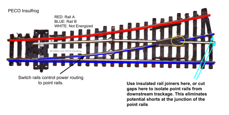
I mentioned that my Peco Insulfrog turnouts are powered by feeders on alll three ends of each turnout. That being the case, all of the rails are powered on each turnout. Only the plastic frog is dead.
Unfortunately you’re trying to do two things (Hand-thrown PECO InsulFrog turnouts and somehow detecting turnout position for signals) that are entirely incompatible with each other.
Sorry, but I don’t see any other way to say this. You can’t do what you want here without controlling the switches with a different throw system.
the images suggests that only one point rail is powered, depending on position. If true, wiring it in series with a (~10k) resistor and detector would allow you to determine tunout position from which you could control a signal.
If the Insulfrog is powered only on the stock rails at the tail end of the turnout, only the point rail touching its stock rail is powered, thus power routing. I guess that this would be useful for dead rail sidings.
However, when the Insulfrog is powered on all three ends of the turnout, as in my case, both point rails are always energized, effectively defeating the benefit of power routing.
Yeah, I am coming to realize that. The micro switch suggestion made earlier in this revived thread is something that I need to take a look at as I move forward.
Such a thing is definitely possible, but by the time you build the electronics, just using a simple snap switch pushed by the throwbar when moving the points by hand is far simpler.
if you had a power routed frog, all you would need is an LED and series resistor between it and one of the stock rails. The LED would be lit when the frog is powered from the opposite rail.
in this case, an LED and series resistor connected to a power routed point rail and the opposite stock rail would indicate when the points rail is powered.
In the dark ages of DC and power routing hand layed all rail turnouts, if we did not want the turnout to control the siding, we simply gapped the two frog rails past the frog, and ran a jumper or second feeder to the track past the turnout.
The route not selected would have both rails the same polarity up to the point of the gap in the frog rail - no problem.
But I will no longer rely on turnout points to conduct power, and I prefer the Atlas wiring scheme as it works better with my control system, the reasons why are too complex to explain here and are part of the automatic train control feature of my control system.
So as explained above, even my manual turnouts are connected to electrical switches which perform a number of functions depending on the situation.
It has become obvious to me that I do not have a switching device on the Peco Insulfrog to trigger the red/green LEDs on the signal.
Had I bought and installed Peco Electrofrogs, I could have used the powered metal frog as the switching device. But I chose Insulfrogs over Electrofrogs because the Insulfrogs were each $3.00 cheaper and a lot easier to install without the need for gaps. I don’t regret that choice.
And I sure did not want to install 60 to 70 Tortoises. So, I chose spring loaded Pecos over Tortoise controlled Atlas turnouts.
My feeling is that since the Pecos require manual action to throw the spring loaded point rails, what’s the big deal about using the same finger to activate the signal. After all, even with the Tortoise controlled turnouts, I still needed to flip the toggle switch on the DPDT on my last layout.
The one flaw in my plan is that I could forget to activate the switching device, resulting in the wrong color LED on the signal device. However, if I use a SPT toggle mounted on the fascia, I can install a bi-polar LED right next to the SPT to show which way the point rails are thrown. So, that is probably the way that I will go with the signal plan.
Peco has two types of contacts that can be mounted below their turnouts but both supposedly require a Peco turnout double solenoid motor to mount them. I wonder how difficult it would be to mount them without the motor? You would have to glue a pin into the sliding part of the contacts which would then go through the throw bar.
Here is the less expensive unit. This one is just glued to the bottom of the motor so making up a mounting plate shouldn’t be hard at all:
OK, I have the fix! This works, I tried it this morning.
I used a brass 0-80 x ½” or 13mm screw through the moving tie. Fit perfect no, threading necessary. I used a pair of .02” Bronze rods as contact levers.
As always click twice to enlarge.
A small #30 super flex wire soldered to the screw will allow easy flexing, the movement is less than ⅛”.
With the bronze rods anchored at 2” there is very lit
To make it a bit smaller .01” bronze rods would work at 1” from the screw. You don’t need large wire for lighting LEDs so smaller spring bronze wire would work. I was thinking of using CA to attach the rod to a small square of Styrene then CA to hold the Styrene to the bottom of the ties.
It would require a shallow groove in the cork about ⅛” deep but should be very reliable, just make sure the screw puts a bit of pressure on the rods.
I’m no electrician, but Mel’s idea makes sense to me (maybe that’s why?)
If I’m thinking of this correctly, sliding a point rail against something metal activates a separate circuit that changes the sitting green signal to red, or visa versa. The circuit doesn’t run through the rails at all, making insulfrog vs electrofrog or power routing issues moot in this situation.