What troubles me about what I call “mechanical” solutions to the problem is that they are prone to fail. The beauty of an “electronic” solution to the problem is that it is not likely to fail since it does not depend upon physical forces.
What I should have done, if I care to second guess myself, was to install Peco Electrofrogs, not Insulfrogs.
Even using Electrofrog turnouts woudn’t completely solve the problem. If installed unmodified, you would get the electrical switch action, but it would be relying on the point rails contacting the stock rails, bot to light the signals AND power the raisl through the turnout. Not a reliable way of doing things at all.
I’m using Electrofrog on my new layout, all modified using the jumper points to isolate the frog for independent powering, and tying the point/closure rails to the adjacent stock rails. By the time I get that far, the Code 70 stuff should be readily available, so I am plannign on using that for sidings and yards. Those are expected to all be the new Unifrog design, but given that these will be areas traversed by smaller locos, at lower speeds, I will probably at the very least make arrangements to power even the small insulated section of frog, even if it turns out I don’t need to hook it up to anything. That worked out well on my last layout - every turnout was pre-wired to power the frog before installation, and then it turned out I had quite reliable operation without actually hooking those wires up.
That would work of course, but the whole reason for installing Pecos was to to be able to take advantage of the spring loaded point rails, so that I can throw them with a flick of the finger.
I like Dave’s idea of using the Peco contacts. The contacts, like their solenoid motors, are free moving - they don’t have over center prints or wipers to hold in position like a regular switch, or like an Atlas solenoid motor, because the over center spring to hold the points to one side is part of the turnout itself. So by rigging the Peco contacts to the throwbar, you gain the electrical contacts needed to operate signals or whatever, and still have the manual push the points control of the turnout, no additional electronics needed.
Yes, you would have to clear a space below the turnout. The Peco motors and the contacts both are designed to hang off the bottom of the turnout under the throwbar. Depending on how thick the contacts are, you might get away with just clearing the space in the roadbed, unless you are laying the track right on the plywood. You’d need to clear space under the turnout for Mel’s DIY method as well, but it’s effectively the same thing.
Another way would be to combine the methods - a small protrusion down from the throwbar like the screw in Mel’s example, impacting on a snap action switch laid on its side. I’m pretty sure you can get ones thin enough to fit within the thickness of cork roadbed. In one position, the lever of the switch would be released, and the normally clsoed contacts woudl be active. Flip the throwb
This is pure speculation, but I wonder if either of the Peco switches could be mounted below the subroadbed with just a small hole required to make space for the rod that links the throw bar to the switch. The rod would have to be mounted securely in the hole in the switch so that it moves the contacts as the throw bar moves, but I don’t see why the Peco switch has to be right tight to the bottom of the turnout.
Something that I would suggest is to mount the Peco switch on a larger piece of thicker styrene. With somewhat oversized holes in the styrene and washers on the mounting screws, the switch position could be easily adjusted to make it work properly.
On my last layout, I used Atlas Custom Line turnouts, powered by Tortoises. One of the internal switches on the Tortoise controlled the signal associated with that turnout. This system worked flawlessly.
On my new layout I decided to use Peco turnouts because the idea of a spring loaded turnout really appealed to me, and it eliminated the need for a Tortoise to control point rail movements. A significant advantage of this arrangement is the elimination of under layout turnout controls. No drilling, no laying on my back to install motorized devices.
I don’t intend to reverse that decision at this point. For that reason, I revived this thread to learn if there was an electronic solution. By electronic solution, I mean a method of wiring alone that will power the signal. It does not appear that such a solution exists with the Peco Insulfrog.
The only problem with this is the Peco points are the power pickup for the power through the turnout.
I have one Peco Insulfrog working using the points to power the turnout rails for about four years and never had a problem, it is powered with a PL-10 switch machine not hand thrown. Even though it’s switch machine operated it would work the same because of the Peco spring.
then, isolating one of the point rails from the other end of the turnout, relying on the power routing mechanism (tab or otherwise) of the turnout and attaching a wire to that rail provides a signal indicating turnout position.
The Peco I have is new in the package and the point rails to side rails don’t measure 0 ohms, just over 1 ohm (Fluke 179). I’m not sure whether they will work well enough to pass power to the locomotive. The Insulfrog doesn’t have the contact wiper on the point rail.
EDIT:
The resistance must be between the plating on my meter probes to the nickel silver rails. It measures the same resistance on the single straight through side rail.
But I think all on/off switches rely upon physical forces. Point rail to stock rail contact is physical force, as is what ever makes contact within those little plastic boxes we call switches. When we press a button or flip a throwbar, something inside the box touches something else. How else does electricity know which path to take?
Its seems like you’re trying to use the rails of the turnouts themselves as the signal’s on/off switch. I think there is another way, but the specifics of how to build it are above my pay grade.
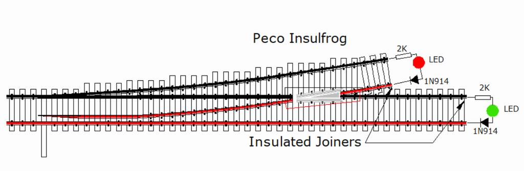
I got to thinking more about my own observations relating to the behavior of the Insulfrog. If only the tail end of the Insulfrog is powered, the power routing feature works. But if all three ends of the Insulfrog are powered, the power routing feature no longer works. So, I gapped the two non-tail ends of the Insulfrog. With the gaps in place, I was able to power a signal off the rails, using DCC power.
However, this only worked in certain situations. I could successfully power my dwarf signals which used separate red and green LEDs. But, I failed to power my search light signals which use a bi-polar red/green LED. The problem arises with the common wire.
With the dwarf signal, I can pigtail the common wire and connect it to the opposite rail on both the straight through and divergent routes. But when I do that with the search light signal, the bi-polar LED turns amber on one of the routes.
Any suggestions with how to deal with the common wire on a bi-polar LED setup?