No, I do not have any diodes in the signal wiring, but I wonder if diodes are the solution to the bi-polar LED wiring. I wish that I understood more about such wiring.
When you say that you are concerned about voltage drop, are you saying that powering the LEDs off the rails may pull too much power from locomotive performance?
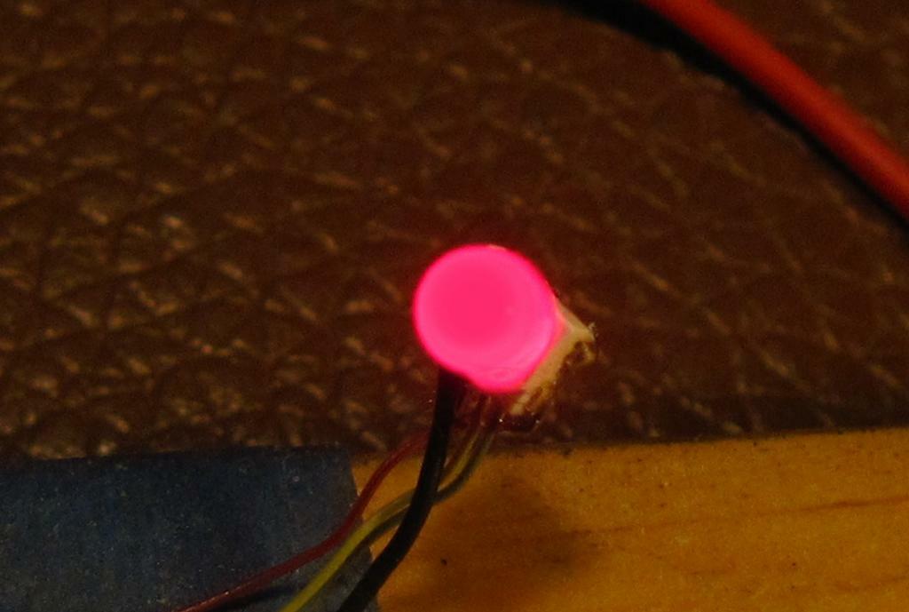
Not a good thing. What is happening is that instead of turning from red to green, it is trying to show both colors and it turns out an orangey color which is why I referred to it as amber. I need a way to block the green LED when the red LED is activated. The search light signal is a bi-polar red/green LED, no yellow.
OK, I found the solution to the bi-polar LED issue.
By placing a diode in line with the Green LED wire, I can prevent a current backflow that was turning the red/green LED to an orange blended color.
Now, my only concern is bleeding off too much DCC power by wiring the signals to the DCC-powered rails. I do have a RRampMeter hooked up to the layout, so later today I will check the effect of voltage drop. One or two signal hookups should not matter, but I have a considerable number of signals to wire up, so voltage drop may be a serious issue. Any thoughts?
I just tested with my RRampMeter. Each signal draws 0.01 amp. That would mean that it would take 100 signals, more than double what I need, to consume 1 amp of DCC power. Wouldn’t that be acceptable?
I agree with Mel. Increasing the value of the resitors will not only save you some power, but you may also find that the brightness of the LEDs is toned down to the point where they don’t burn your eyes if you look straight at them. I have seen some signal systems where the LEDs were so bright they were almost blinding.
I’m working on tri-colour signals for a friend. I’ve only worked with tri-colour LEDs once before and those were for classification lights so having them bright wasn’t too much of an issue. I’m curious to know what value resistors you are using.
You have better vision than I do, at better than 30 years older than me. No way can I do those super fine wires on SMD devices. And unfortunately nothing can fix that, I’m for the most part only seeing out of one eye, so it’s not just the sharpness, my depth perception is off.
Are those the RGY LEDs from RR-CirKits? The ones he sells have a perfect aqua green for railroad signals - the typical green LED is WAY off. You might not notice it until you see what one of the nice ones looks likes.
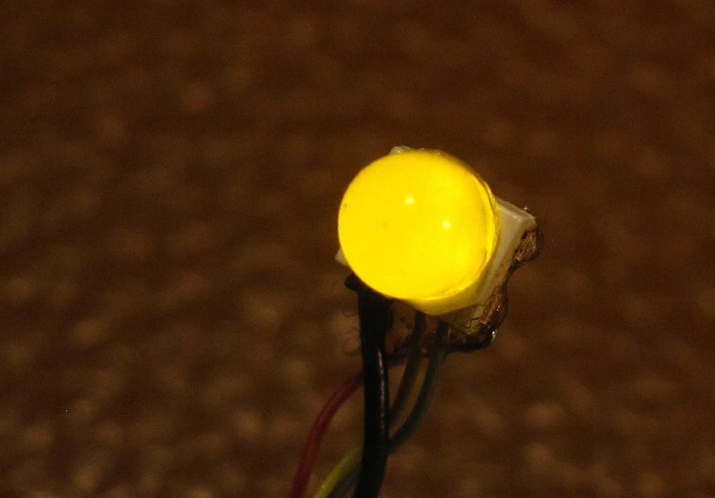
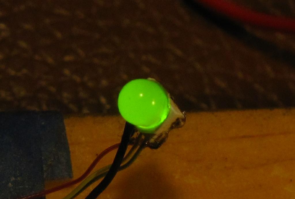
Do you have a picture of the green indication? The LEDs that I am using for the club’s signals are about $4.00/100. The Canadian price for 100 of the LEDs that you are suggesting is $155.00 incl. tax and shipping. I’m not happy with the green tone on the cheap LEDs but I’m reluctant to spend that much money unless the green is hugely superior.
All of this talk about about milliamps prompts me to ask, how do you determine the amount of milliamps on an LED. I have seen various reports stating LED current draws to be 20 to 30 ma without a resistor attached. Is there a way to measure exact milliamps for a specific LED?
20ma is typically the max. But over the years, LED optical intensity has increased. The value for different color LED and manufactures may be different.
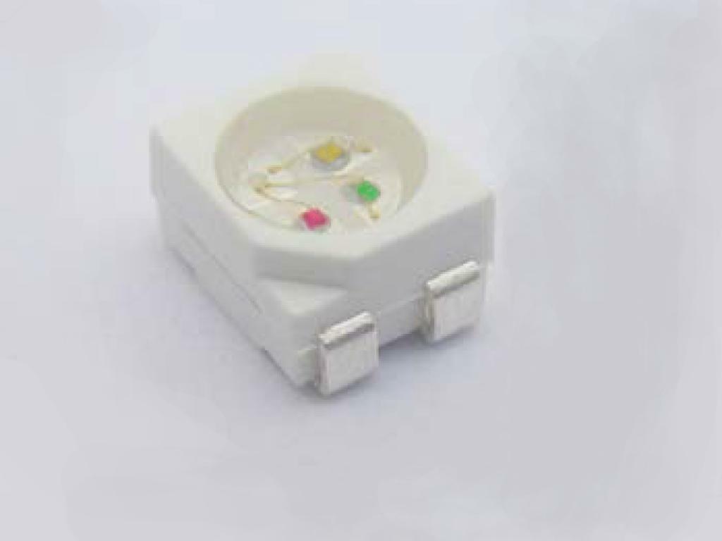
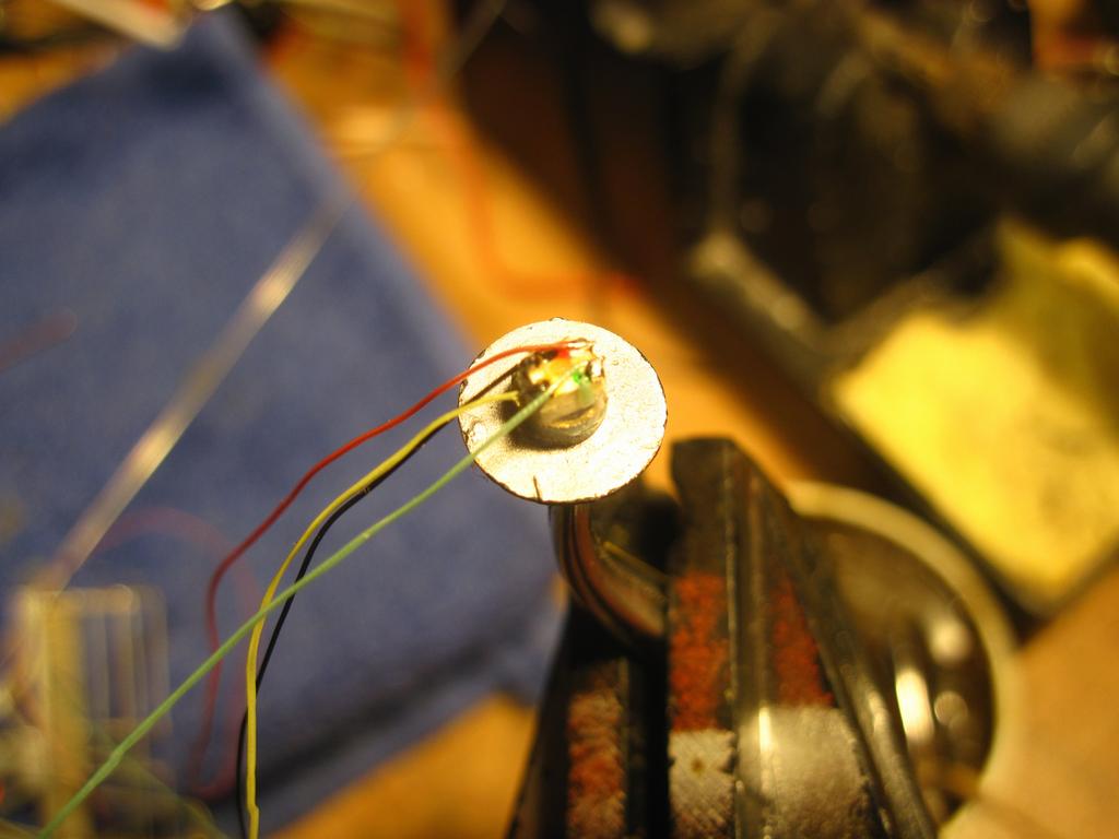
I’m not very good taking pictures but I tried on the SMTL4-RGY
I had used three wire bi-color LEDs for my first signaling system about 20 years ago and they worked out great. When I was in the designing and planning portion of my current project I wanted to go with common Anode. I also used the brass tube of the signals as common, I never liked the idea of having an “electrically hot” pole that close to the tacks.
I tried several batches of the newer three wire bi-color LEDs in both common anode and cathode all had unusable yellow color and pitiful at best green. I went into search mode for months and finally ask on the Forum. Randy suggested a