I do not run DCC. The title of the forum also says “electronics”, so this seemed like the right place for this question.
.
Is there a DC power pack currently made that has a Pulse Width Modulated output (PWM) to control the trains. I am pretty sure the MRC Tech II model 2500 was a true PWM pack, but I have not read anything about the current production packs being made like this.
.
I would suspect that some must be. PWM is used to control fan speed on your car’s A/C blower, actuator position for fuel pressure regulators, and all kind of other things. I just cannot seem to find verification.
.
I found a couple packs that say their output is “pure filtered DC”, but that is only half of what I want. I also want the DC not to be variable voltage, but PWM.
MRC advertises the Tech-7 packs with “Accutech” and “Proportional Tracking Control”, but I cannot find a description.
.
They also have a note on their DC power pack page that says the 1300 and 1370 might not be compatible with DC locomotives manufactured by Rapido. Is this because the 1300 & 1370 are PWM?
Kevin, I’m also running my layout DC, using an MRC ControlMaster 20. Rather than the throttle that came with it (adequate, but not much finesse), I use a hand-held PWM throttle from this guy. Mine is the 3 amp version, with the same handheld as shown in the first picture. It offers great speed control and I’ve operated over a dozen locos at a time using it (my grandkids got a kick out of seeing them chasing each other around the layout).
I do run heavy trains with multiple locomotives, though, and the set-up handles it with ease. I’ve done mine so that I can use standard ‘phone jacks as plug-ins on the layout’s fascia, in various places, and have a 30’ springy-type handset cord that I use to connect the throttle.
The circuit board will run from either an AC or DC supply. I picked mine up in-person, as his workshop is only about 15 miles from here.
i know this doesn’t confirm your question specifically for the MRC Tech 2500. I didn’t find anything search for MRC and PWM.
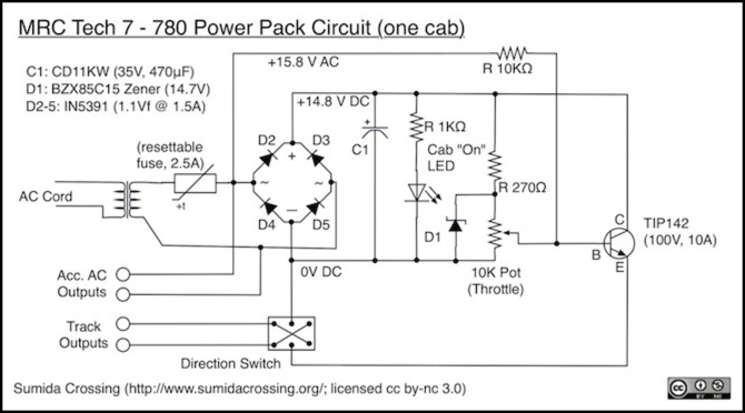
the schematic below for the 780 describes a simple transistor throttle, meaning regulated output. It also leaks some of the 60 Hz AC waveform into the output. As you probably know, these pulses help overcome motor resistance at slow speed.
one characteristic of PWM throttles is that there is no need for a heatshink and they can be a very simple circuit board
Is the momentum always on, or is there a way to turn it off? I really do not like operating with momentum and/or braking. I know it is more realistic, but I like to be in control.
My understanding is that the use of PWM in small DC motors like we have in our trains, heat increases in the armature during slow speed use…as much as 5 times more than plain DC variable throttle, there by shortening the life of the motor and brushes. If You have the time…read thru this link…talks about PWM and all kinds of power packs/throttles:
The circle on the right is a transistor. The B the input that determines how much power is allowed to go through the transistor to your track. When you have the throttle turned all the way up, the power goes to the ground instead of the base. No power at the base pin, no power going through the transistor.
There’s a natural resistence to keep the field from collapsing when the power is removed. Whenever you have resistence to something, heat is generated. But this is NO problem for a quality motor as long as you aren’t constantly reversing the voltage on it. +/12 V swings can play havok then. Not only are you trying to collapse the field, but reverse it.
The output of DCC decoder is PWM, and I (and a number of my friends) have been using the Aristo Train Engineer in PWM mode for over 20 years with no ill effects.
When I was wiring factories 30 years ago, all the fine speed DC motors for production lines were PWM controlled.
i don’t know of any DCC decoder that doesn’t use pulse or PWM to drive the motor. If the didn’t and drove the motor with DC, they would need bulky heatsinks
pre-transistor throttles simply had a rheostat in between the transformer and motor to control the motor voltage. The problem with this is that the more current the motor drew, the more voltage and power were dissapated in the rheostat, reducing the motor voltage.
in a bipolar transistor (not FET), the base-emitter looks like a diode with a voltage drop of ~0.7V. The collector-emitter current is proportional (x50) to the base-emitter current. In this configuration, the emitter is the output connected to the track thru the DPDT switch
In this configuration, the transistor regulates emitter current to maintain the voltage at the emitter at the base voltage less 0.7V. If the emitter voltage drops, the base-emitter voltage and current increases, increasing the collector-emitter current. The opposite happens when the emitter voltage increase.
in other words, the 10K pot determines the voltage at the track and the zener diode, D1, maintains a constant voltage across the pot, independent of the transformer voltage.
[quote user=“DigitalGriffin”]
There’s a natural resistence to keep t
Momentum is preset, not quickly changed. I keep mine on zero because even the “zero momentum” setting has a “ramp up/ramp down” speed as the throttle is push button, not a rotary knob.
Hold the Faster button train accelerates, hold Slower, train decelerates.
If you reverse the direction while the throttle is active, it will first ramp down to zero, slight delay, change direction, ramp up to previous speed setting.
It has an “emergency” stop button, kills the signal pretty quick.
Throttle does not come with a power supply, you choose voltage and amperage suitable to your scale. It will handle 20-24 volts, 10 amps. I use 13.8 volt regulated at 4 amps. You must have a seperate power supply for each throttle - no common rail.
With most locos it will light headlights at full or nearly full brightness before train moves.
One a loco moves, they virtually never stall. Slow speed starts are very good, similar to DCC, very smooth start/stop.
I did a lot of testing before adopting them for my layout. I use them as part of an Advanced Cab Control system with signaling and CTC.
This is an interesting topic Kevin. I run dual mode on my layout, DC or DCC.
I have two MRC DC controllers and never checked their output with a scope. The TECHII 2500 and the Sound and Power 7000 are both PWM. Unloaded the 2500 will put out 19.2 volts measured with my Fluke with the throttle at Full. The Sound and Power puts out 17.6 with the back switch in HO position and 21.8 with the switch on G gauge.
The 2500 has an excellent square wave, better than the 7000 and both are extremely clean. I was amazed.
Mel
Modeling the early to mid 1950s SP in HO scale since 1951
&nb
The link I provided has a different opinon on PWM…pertaining to heat and what PWM actually does. Who is correct? Click on the link and scroll down to " Pulse Control and Motor Heating". Not doubting anyone’s opinon on what I said…just how it is accomplished and the results.
I personally use MRC CM 20’s on my layout…the newer ones without the fan and never had any problems with them…including their hand held, with a spare, that I never had to use. I also run DCC engines with sound on the layout, mostly for the Grandkids…I can live without DCC.
The key with PWM is it depends on the frequency of the pulses. Even coreless motors, which have no nice solid metal armature to dissipate heat, are fine with PWM - as long as it’s of a sufficiently high frequency. ALL DCC decoders put out PWM. The ones that say they are ‘silent running’ or ‘supersonic’ use PWM frequencies above human hearing, and are capable of driving a coreless motor safely. Not many off the shelf locos have coreless motors though - some high end brass, and those new Kato locos with the motors integrated in the trucks. Old decoders in the early days of DCC didn’t use high frequency drive, those could and did make motors bizz, particularly types where the magenets weren’t glued in, like Athearn ones with the tan/gold case. It was cautioned not to use these types of decoders with coreless motors as it would overheat and damage them.
Higher PWM frequency prevents the motor heating, but the downside is it causes the motor to develop much less torque at low speed (short pulses). Decoders include a ‘kick start’ to increase low end torque (some brand call is torque compensation). There’s no reason a DC throttle circuit using PWM couldn’t also do all of this.
Also, while most DCC decoders can operate with DC or DCC, if set that way, they often are confused by DC PWM control, the PWM square wave looks too much like DCC and the decoder thinks is is on DCC track, not DC. So a PWM throttle is not a good option if you want to run locos that come from the factory with DCC decoders in them. For best results, the decoder should be removed and bypassed.
not sure where there’s a difference of opinion on how PWM works.
one thing several quick searches pointed out is that there’s a difference between running PWM at a low vs high freq (same duty cycle) and why.
the inductance of the motor resists a change in current. So at low frequency (100 Hz), the current thru the motor increases to max during the PWM pulse and has a chance to drop to zero when the pulse is off. This translates to more resistive heat being generated during the pulse at max current.
at higher freq (150 kHz), the pulse switches off before the current has a chance to change much and similarly, does not decrease much when the pulse switches off. In other words, the current is relatively constant, although varies, with PWM at high frequency. This means the motor can see a current and voltage similar DC with PWM at higher freq.
i believe todays decoders operate PWM at higher freq (200kHz).
monitoring BEMF allows the decoder to make adjustments to provide good low-speed performance
i don’t know enough to understand the heating effect differences with PWM freq. I couldn’t access the IEEE article referenced at the bottom of the link.
let’s assume the motors do run hotter with PWM. I don’t believe it is cumulative in the sense that it wears the motor out. I believe increased temperature can cause the wire insulation to melt and is only a problem if there is a short. Until there is a short, there is no loss of performance.
i don’t know what is the melting temperature of the wire insulation is nor how close to that temperature our locomotive motors are getting due to PWM.
the fact of the matter is that motors are being driven
zstripe
My understanding is that the use of PWM in small DC motors like we have in our trains, heat increases in the armature during slow speed use
i don’t know of any DCC decoder that doesn’t use pulse or PWM to drive the motor. If the didn’t and drove the motor with DC, they would need bulky heatsinks
DigitalGriffin
I’m pretty certain that’s standard DC.
pre-transistor throttles simply had a rheostat in between the transformer and motor to control the motor voltage. The problem with this is that the more current the motor drew, the more voltage and power were dissapated in the rheostat, reducing the motor voltage.
DigitalGriffin
The circle on the right is a transistor. The B the input that determines how much power is allowed to go through the transistor to your track. When you have the throttle turned all the way up, the power goes to the ground instead of the base. No power at the base pin, no power going through the transistor.
in a bipolar transistor (not FET), the base-emitter looks like a diode with a voltage drop of ~0.7V. The collector-emitter current is proportional (x50) to the base-emitter current. In this configuration, the emitter is the output connected to the track thru the DPDT switch