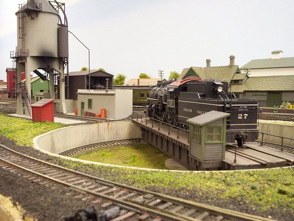
Please forgive me for posting this photo again. I have had it in my computer for a few years as this is what I wanted my service yard to look like when I finally got a layout to the stage where it might actually happen.
I am at the stage of laying out the track and laying templates of where the buildings will go.
This is a C.P.R. yard in Vancouver and was like this (a very dirty industrial area) up until the 1970s. I remember going to this area as a 20 year old in the mid 70s on work related trips. Soon after that it became the sight of Expo 86 and then turned into a pristine residential area.
This photo was taken in 1916 and I am modeling the 1950s so some modernization will have to take place though more on the steam side rather than diesel.
I just have some questions about what I see in the photo and how things may or may not be included on my layout. Any suggestions, additions or removal of things that wouldn’t be there in the 1950s.
Note; the small pics were cropped out of the large photo. I couldn’t enlarge them so please refer back to the large photo.
In this full size photo there is a track running a circle around the roundhouse. I have seen this in a few photos of different roundhouses. Is there a purpose for this track around the roundhouse?
I am not going to build a coaling trestle but am curious as to the grade of it. Any guesses?
What is this tower for? It looks like a hose tower that you would see at a fire hall.
Here are some sand bins. How would they have been filled? I don’t see any conveyor system to fill them.
In front of the sand bins on the other side of the two tracks there appears to be a small crane. I don’t think it’s a water stand as it doesn’t look like the one near the turntab
Can’t make out the tiny photos, but the probable balloon track would be for turning locos without using the turntable and to turn whole or parts of trains, and the grade to coaling facility is probably something like 4% or a bit more (photos can be deceptive).
That is a fantastic picture. Thanks for posting it. There is an awful lot of detail there and it’s fascinating to just look at.
The track looping the roundhouse is indeed a baloon track. I haven’t seen one quite this tight before, but they could be used (as said above) to turn locos without using the turntable. Also, my understanding is that they were often used for passenger equipment to keep certain cars facing the right way (I hate it when the observation car is 'round backwards). Also, some roads turned their sleeper cars. It’s a lot easier to lash a bunch of them up behind an engine and turn them rather than one at a time on the turntable or taking a whole bunch through a wye.
And what’s also interesting is the balloon track crossing the multiple tracks leading to/from the turntable. Normally, the balloon track is oriented so it approaches the turntable/roundhouse area roughly parallel to the turntable lead tracks so tracks need not be crossed.
Mark, the tiny photos are just crops out of the large one. I thought it might make what I was asking about clearer when referring back to the larger photo. Thanks for the input.
The only thing that comes to mind for that tower is maybe it’s some sort of yard observation tower. I would need to be that high possibly to see the entire yard from one spot?
As Mark mentions, the sand would have been moved by shovel technicians. I dunno about the crane across from the sandhouse, but the small overhead one beside the roundhouse may have been for changing-out trucks - lift one end of the car, roll out the trucks (probably utilising former shovel technicians specially-trained for this high-tech job), then roll a new truck into place. There’s an awful lot of spare wheels sitting around - looks like a model railroad where the owner is swapping-out plastic wheels for metal ones. There’s even a Tichy wheel car, and one of their wreck cranes visible, too. As for that tower, my guess is that it actually is a hose tower. In the days when the photo was taken, fire was a very real threat: accounts of the day often refer to a structure as later being destroyed by fire or as being a replacement for an earlier one which had burned. A large terminal such as this would most likely have its own fire department. On my layout, I give a nod to the fire danger by spotting hose/hydrant sheds around the railroad’s facilities: Wayne
After looking at some aerial photos of the time, that appear to be taken from a biplane. The width of the yard is just about what you see and is do to the geography of the area. The yard is very long though.
The balloon track is probably in the only place able to accommodate it in the narrow yard.
Wayne, I think you are right as far as the crane being used to change out trucks. It makes sense.
As far as the hoses. Would they use hoses to wash the engines and other things, thus needing to dry and store them somewhere? I don’t see a drive through wash facility anywhere. If they even had such a beast back then.
Another thing I noticed is the lack of ballast. It looks like they just used dirt.
I count about 17 car lengths for the grade of the trestle (leaving out the top apparently flat section). 17 cars times 40 (nominal length over couplers) is 680 feet. The height looks to be roughly 30’. So the grade is (roughly) 4 1/2 %. As stated by a previous poster.
At the time of the photo, the cars would’ve most likely been 36’-ers. The CPR alone had over 30,000 of their 36’ “Dominion” boxcars. It’s hard to tell with the panoramic view if the trestle is indeed level beyond the coaling station - a common practice was to spot several loaded cars beyond those over the coal pockets. As more coal for the bins was required, workers could release the handbrakes, allowing fresh loads to be re-positioned over the coal pockets as they rolled down the slight incline between the pockets and the end of the trestle. Of course, the brakes would need to be re-set, but this saved waiting for a loco for a re-spot. On closer inspection, it looks as if there may also be a dump for sand right at the end of the trestle. The boys with the shovels would still be required to get it into the drying shed, though. There also appear to be other bins between that and the coaling station - perhaps coal for caboose heating and also for the various sheds and switch tenders’ shanties around the facility. Wayne
The usual practice was to use the interior length to describe a car. So, a “36-foot” boxcar would be about 40 feet from coupler to coupler. For passenger cars, it was the interior length between vestibules, if any. Thus, a 60-foot coach with vestibules at both ends could be something like 67+ feet long overall.
The tower certainly looks like a hose tower. A number of the major shop facilities on CPR had their own internal fire department, even including fire trucks (often second hand). So I would be reasonably confident that is indeed what it is.
The balloon track is definitely unusual the way it crosses the lead to the turntable. Running one around the back of the roundhouse was the more normal method, and could often be found where passenger trains needed to be turned. CPR’s John Street and CNR’s Spadina roundhouses in Toronto both had this feature, as did CPR’s roundhouse at the Glen, in Montreal. After CP’s John Street loop was severed by redevelopment, a daily feature was watching two switchers at work. The first pushed the cars of “The Canadian” onto the turntable, the other pulled them off on the second lead after they were turned, one after the other. There was only one daily train to service so the lengthy process was tolerable. Sleepers and dining cars seemed to have a preferred orientation, not just as the tail end car. Some locations had a nearby junction so the complete trains could easily be turned using the wye connections.
The standard plan of a CPR sandhouse similar to that in the picture indicates that compressed air was used to blow the dried sand up a 2.5" pipe to the hopper. The plan is not clear on how the sand was moved from main storage area into the drying facilities under the sand tower - more than likely manual labour. Locomotive sand has to be very dry to flow smoothly and not clog the delivery pipes.
In the sand bins on the right side there is a box like item. Above it there is a chimney coming out of the roof. Is this the dryer? Would coal be the fuel to run it?
At the back of the roundhouse there is a tall chimney. Is this for the roundhouse boiler?
An Engineer oils his locomotive constantly. His oil can must need refilling often. Where would he get his refills? Is there a tank for this oil on the loco or tender that he can refill his oilcan from? Also at the refueling facilities do we see a onshore tank to replenish the engineers oil?
The chimney will be coming from the sand dryer, but the dryer itself is probably close under the tower itself. There will be a flue leading over to the chimney, since there is obvious fire danger to have it directly under a wooden structure. More than likely coal would be used as fuel, being cheap and conveniently available.
The tall chimney is very likely for the boiler in the powerhouse. It would provide steam heat for the entire complex, as well as steam to speed bringing the locomotives back to working pressure. In early days it might also run a generator to supply electrical power, and stationary steam engines to drive belts for the machinery. In many terminals steam lines would be run over to the station area too, heating the station itself, express and freight sheds, and of course connected to parked passenger equipment.
I can’t give reliable guidance on the source of oil for the engineer’s oil can. I think one full can would be more than sufficient for the length of his run - they had a fair capacity - but that is merely a guess. T


 Wayne
Wayne