(EDIT: Originally “Versatile small layout and track design.” Since this thread has ballooned beyond what I initially asked and become a space for all things related to my MRRing endeavors, I changed the thread topic to something broader.)
Hi everyone,
I’ve recently decided to get back into model railroading after some years away from the hobby-- when I was eight years old, I had a layout my parents built for me, then as a young teen I built one myself-- both HO scale 4x8s, both pretty terrible in terms of operation possibilities but with a continuous run oval (two, in the case of the one I built myself.) As a result I have quite a bit of HO rolling stock to play with, plus a liking for continuous running but also a wish for something more operationally interesting.
I decided to spend the past three months researching (a significant amount of that on this forum-- I’m overwhelmed by the amount of information and resources here) and reflecting on what I really wanted out of the hobby. I like to sit back and watch trains run, but I like operations too and am thinking it might be fun to work with waybills and direct trains both through and local. I like to work with my hands and build/design/create stuff, so I’ve decided this time around to try to scratchbuild some structures, kitbash and detail some of my older, blander Athearn/IHC rolling stock, and build my own turnouts/handlay some of the track (using code 83 flex for the rest.) This gives me lots of individual projects-- time is not really an issue, as I like to take my time putting together these things.
The main problem, however, is space-- specifically, a variable space. I will be moving around a lot in the next few years (my wife and I are both grad students), so I have been spending a lot of my time figuring out how to make a portable layout that could fit into a general space without overwhelming the room, and that, should it be impossible to fit the entire layout into a given space, I can set up a se
There doesn’t seem to be too much to add. I’d say it looks like you’ve been doing some sensible creative thinking and paying attention to some voices of experience. What you’ve drawn is a modified and expanded version of the old Tidewater Central layout that was featured in MR around 1955-56. I’m not so sure about the length of your passing siding. It seems a bit short, but probably workable. Your curves should work out OK for shortline/branchline operation, although there are some passenger cars that might have trouble with 26" radius. For the 1948 time period, I’m guessing you’ll be using steam locos, probably 2-8-0’s. They should be fairly comfortable on a layout like this, and it looks like you’ve done about as much as you can do in terms of portability and adaptability for other locations.
Thanks Tom! Amazing how similar the two are-- I was not familiar with that design. I laid out the passing siding with some templates the other day and it is a bit short-- both tracks will hold 3 passenger cars and loco, but that only works out to 4 freight cars plus loco and caboose. I’ll have to play around with it some more. There may only be room for one engine service track, as well, if I’m to fit the water and sand towers into that area.
Yes, I’ll be using mostly steamers-- a 4-6-2 for passenger traffic, and planning to kitbash two 2-8-0s from my current stock. I have a pair of IHC 2-8-2s and a Mantua ‘Sierra #3’ long-bodied 4-6-0 that seem promising for that task. I also have a little Bachmann GE 70-tonner to use for switching and interchange traffic.
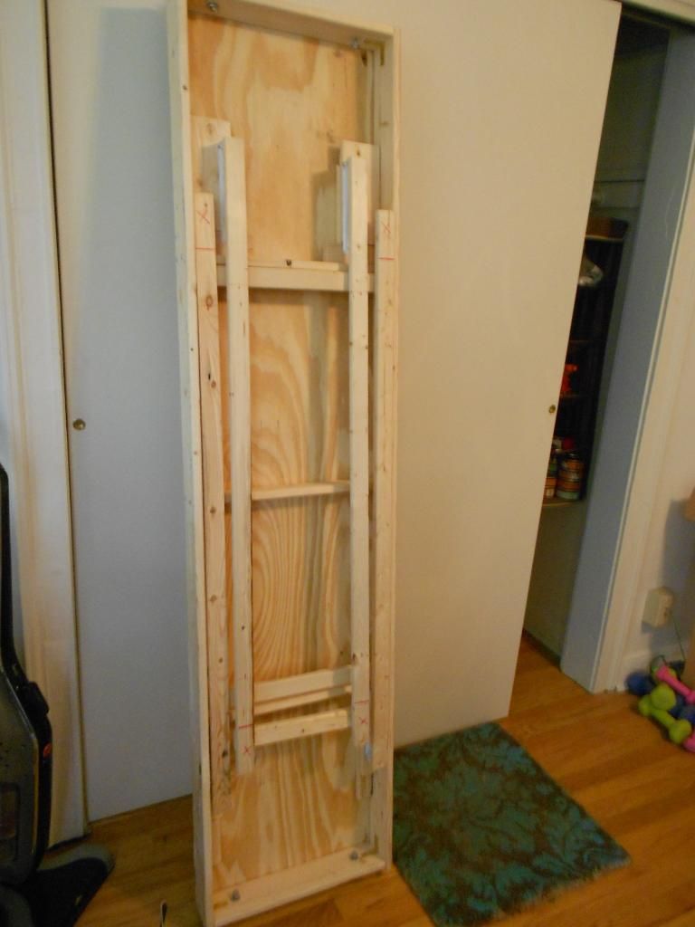
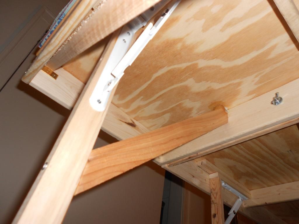
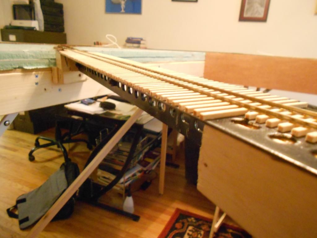
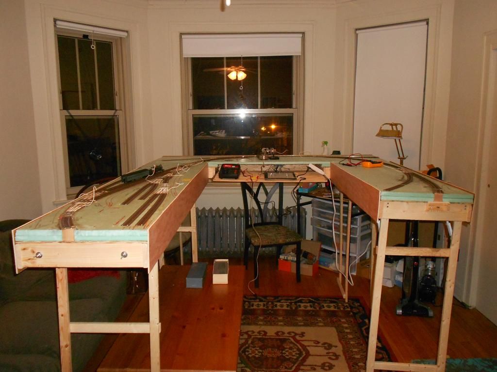
So I’ve decided to turn this into a build thread, and will update things as I go along. In the past month I’ve started on the benchwork, but am having some problems with stability (figures, since it won’t be bolted to a wall.) The sections are designed so that the legs fold in (48" 1x2s attached with folding brackets to the underside of the table.) I will probably shorten these to 44" since I have a four-foot section that needs to reach the same height. Sorry for the fuzziness in these pics:
Frame is 1x4s with 1x3 crossbeams, 1/4" ply on top. The section I have in the pics is 72"x18". When two sections are bolted together into an L, it’s much more stable but still not wobble-free, and standing alone, like this one, it wobbles all over the place. I realize the 1x2s are quite flimsy by themselves, but I’m trying to fit this into a compact space while also keeping weight down. The problem is that since the legs are supposed to fold up into the layout’s undercarriage, a permanent brace across the section’s length won’t be possible, so I’m now thinking about some kind of removable bracing that I can slip onto the lower cross-pieces.
I did not read all of your words about operation. Having jumped to the plan itself, I think it is a good fit for the space and you should be able to fit all of the turnouts where they are shown. That can sometimes be a problem with hand drawn plans.
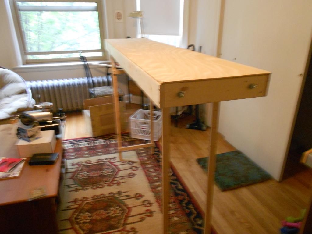
The cross braces are removable and currently held in place by gravity. It’s quite stable, although for extra security I may find a way to lock them in place. I also put 2 layers of 1" foam on top, attached with caulk.
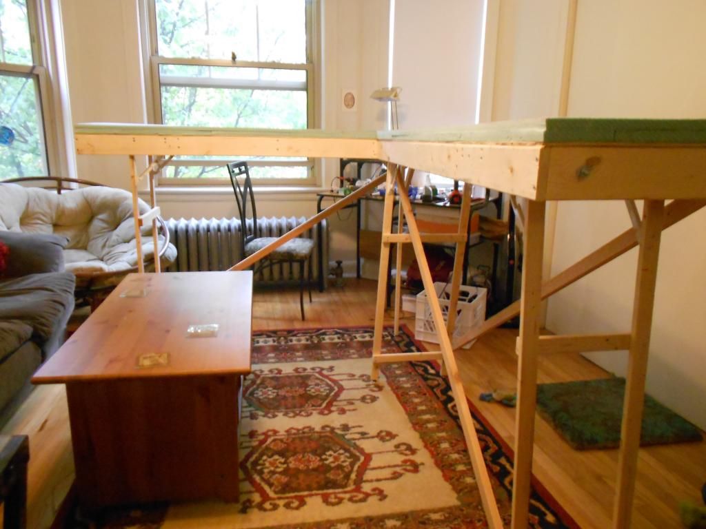
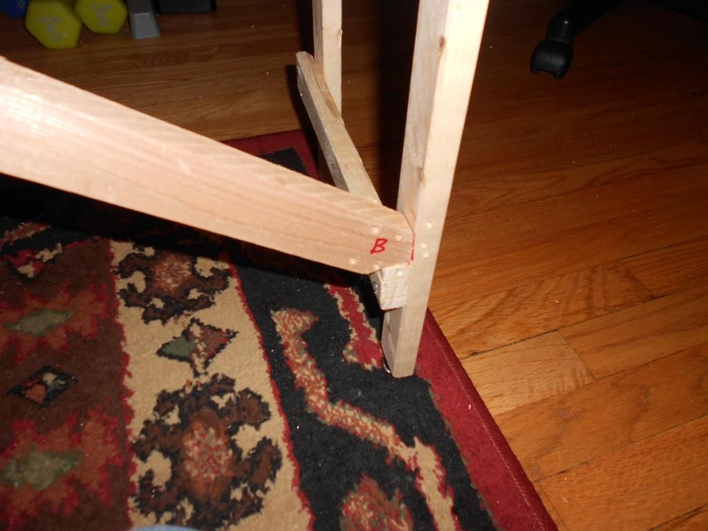
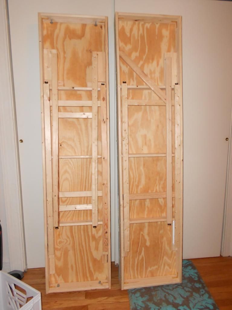
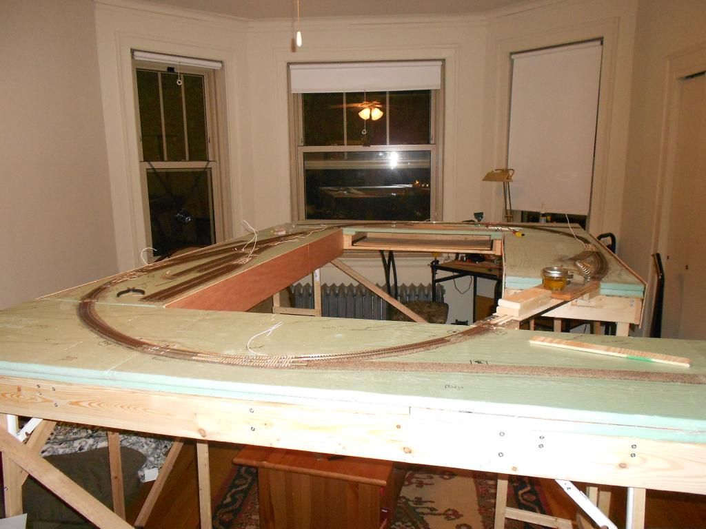
Some close-ups. Notice that the second table only has three legs-- I did that to cut down on weight. Only the center table will have four legs-- I can then build outward from there when setting the layout up. The ‘Y’ shaped brace gives the table enough stability so I can set it up without falling while attaching sections, or if I want to work on it seperately later on. The two sections are attached with 1/4" carriage bolts and wingnuts.
This pic shows a good view of the construction difference.
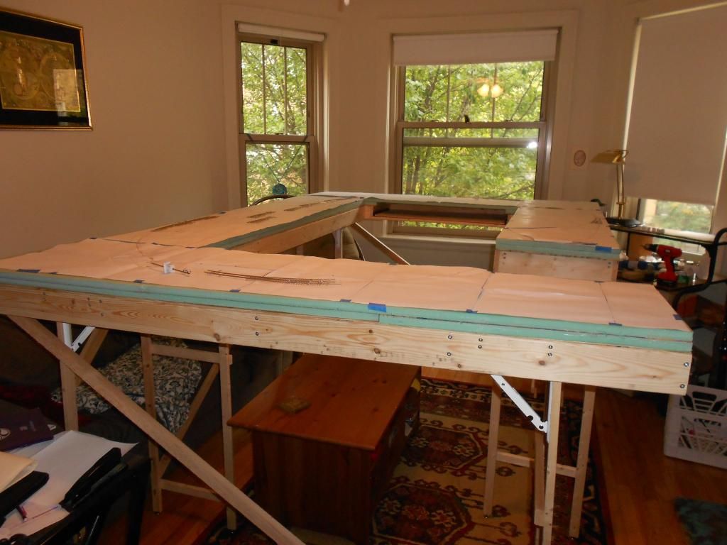
All sections are up and I’ve begun setting out the track plan.
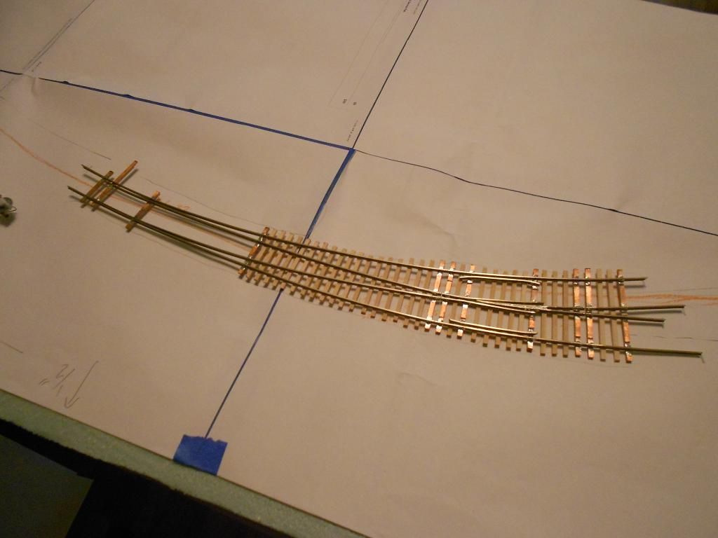
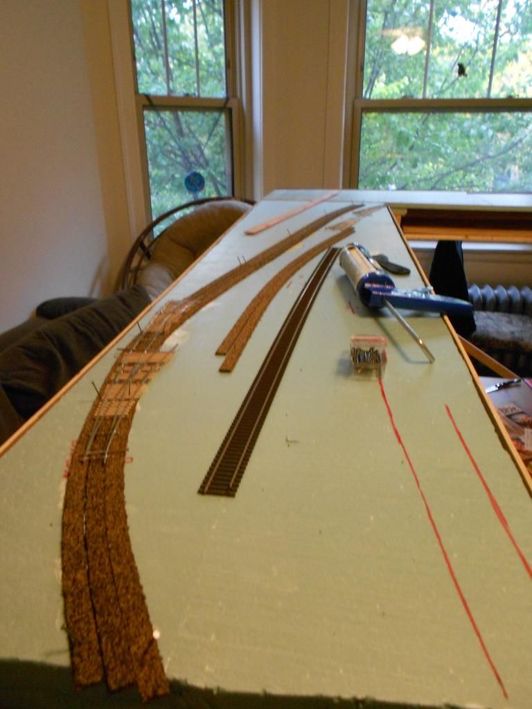
One end-of-summer project, while I was acquiring the materials for the benchwork, was learning how to build turnouts from scratch. I can’t say I’m particularly talented at making them look good, but so far they all seem to work well and easily let single trucks, freight cars and passenger cars roll freely through. We’ll see what happens once everything is wired up and once I start running full trains through them. This is a #10 curved turnout-- most of the other ones I made were closer to #5-to-#7-range.
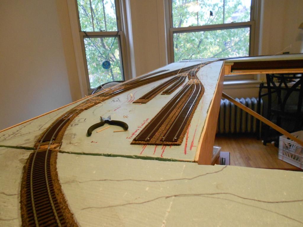
Once the track plan was transferred onto the foam surface with a Sharpie, I began laying out roadbed. I’m using N-scale roadbed for a lower profile.
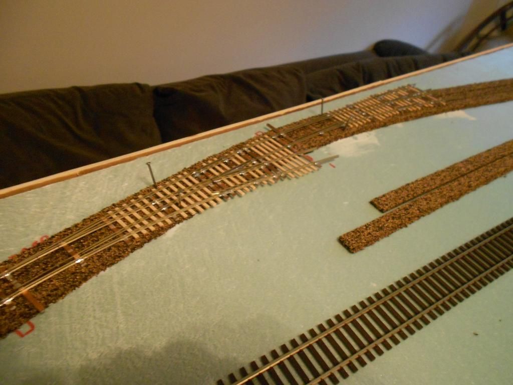
Closer photo of the double turnout leading to both the passing siding and the coach spur for the station. Again, not very pretty (especially unpainted) but it gets the job done for now.
(Terrible flash photo, sorry…!) I asked in another thread about soldering the flex curves and curved turnouts together and decided to solder the whole line, with a few small gaps strategically left for insurance. The freighthouse and maintenance spurs are fixed in place, too (that leaves the coach spur, interchanges and industry tracks, but those should be easy to add in later):
Where the sections meet, I affixed small scrap pieces of wood cut to the same height as the foam plus roadbed. I put two small brass screws into these, then soldered a PCB tie to them, and the rails to the PCB tie. I’ve taken the sections apart and put them back together a couple of times now, and so far it seems to do its job keeping the track aligned.
A while ago, while building the turnouts, I bought some Northeastern Scale Lumber Co. turnout ties thinking they might be useful. It turns out they were the wrong thickness for the PCB ties I was using, so I ended up making some out of balsa. These turnout ties, though, were the perfect size for my lift-out bridge: I bought a piece of steel angle, sprayed it with black paint so the metal would recede into the background, and glued some scrap wood to it to make a base/angled connector to the sections it spans. Then I laid the turnout ties over it and secured the rails with Pliobond.
I plan to use some neodymium magnets to hold it in place and for easy removal. The bridge structure itself will be built up above as well as underneath the track, helping to further hide the steel angle. I have some form of arch bridge in mind, b
Incidentally, I don’t know if anyone is actually reading this or at all interested, but I’m just putting stuff up-- anything related as I make my way through this project. Because I’m a beginner, I’m sure I’m making mistakes here and there (and possibly everywhere…)
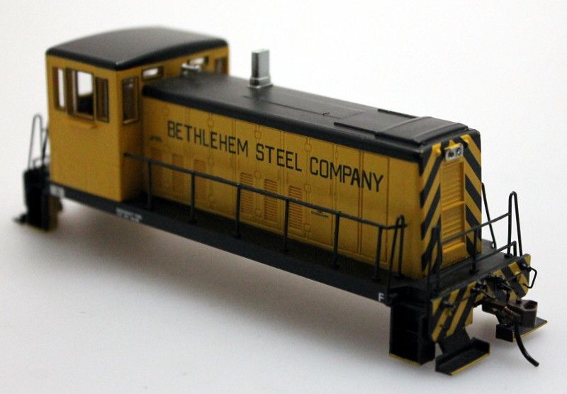
I wanted to put up my first airbrushing experiment: my Bachmann GE 70-ton switcher, which I got off Ebay for about $30, made a great first detailing project because it’s a relatively small and simple engine. I wanted to use this shell:
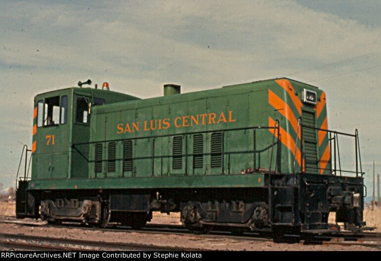
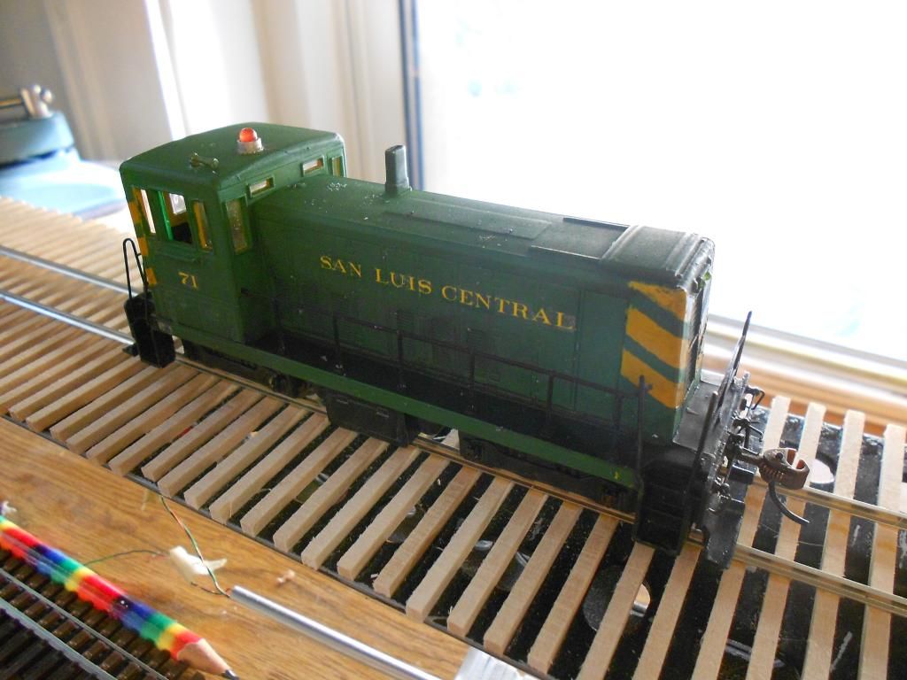
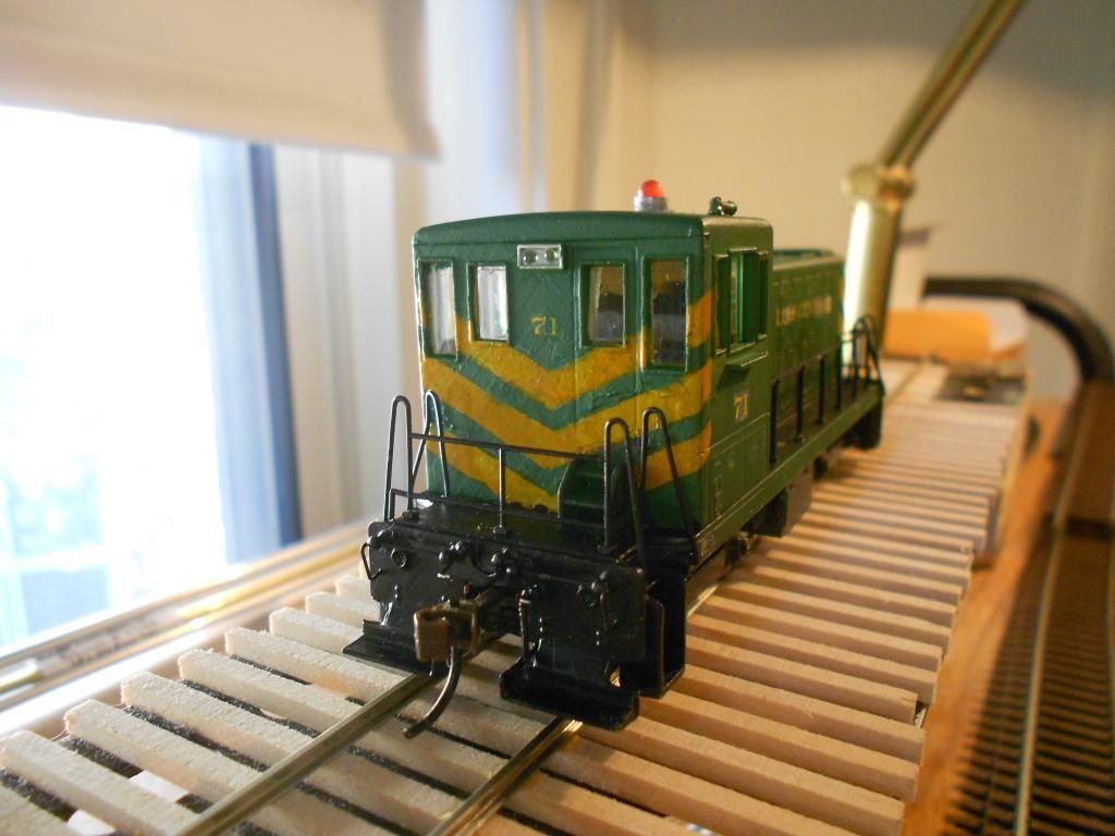
to match the prototype, SLC #71:
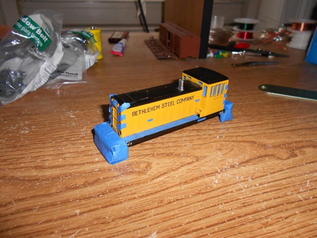
So I masked the shell’s stripes and windows and went to work. In retrospect, it probably would have been better if I had painted the whole front end the stripe color and then masked those and went over it with the body color… live and learn.
Simple small detailing-- I moved the horn to the cab roof and added the red lamp. Here’s the loco as it stands now:
The stripes are not as clean as I would like, there’s touch-up needed there as well as around the cab windows, and you can see the decal films-- I still need to spray it with a clear coat. The colors aren’t an exact match, either. But I’ve still had a lot of fun trying to make this model somewhat resemble the real thing.
I don’t know about anybody else, but I’m reading and enjoying your progress. Most beginners don’t have the focus you have. They tend to try to have a model railroad that does too much. You have chosen a small prototype railroad with a manageable roster. Your scope is a bit limited, which means your expectations are reasonable. But it looks like you are doing very well without a lot of unnecessary input from us. You’ll make mistakes. The technical term for that is “learning”.
I know of the SLC, but that’s about all. In his classic book MIXED TRAIN DAILY, Lucius Beebe tells of the SLC engineer who lovingly dolled up that 2-8-0 with silver trim. I hope to learn more about the road through your posts. Keep’em coming.
All of the ones I’ve got are handbuilt-- I may make a few more for cassettes, but all the ones I need for the layout at this point are finished. Besides the #10 curved, there are a handful of regular #5s and then a few that were constructed together: a pair of #8s facing point-to-point, a pair of #6s in series, and a #6 curved and a #7 straight in series. I designed each of those for a particular space in the trackwork to keep it flowing.
I made my own tie jigs using templates off of Fast Tracks’s site and a few short strips of balsa to hold the PCB ties. The frogs I made mostly by eye, with a flat file, by making a sharp kink in the rail and then filing at it until I’d almost gone through it. Then I bent it back over, soldered the two pieces together, and filed the frog point until it was sharp.
In the last (busy) two months, most of the work I did involved wiring track and checking connections. I’m still going on that, so there’s been little visual progress. I did, however, return home with a couple boxes of rolling stock, wire, and buildings left over from my childhood layouts.
About 95% of the cars are old Mantua/Tyco collected on the cheap, which is great for me because it gives me plenty of fodder for learning how to kitbash, build scratch details, and weather. Also, it’s a trip looking at some of my hilarious attempts to freehand paint lines, details, lettering… I didn’t care about how they looked, I was just being artistic and not trying to match anything in real life.
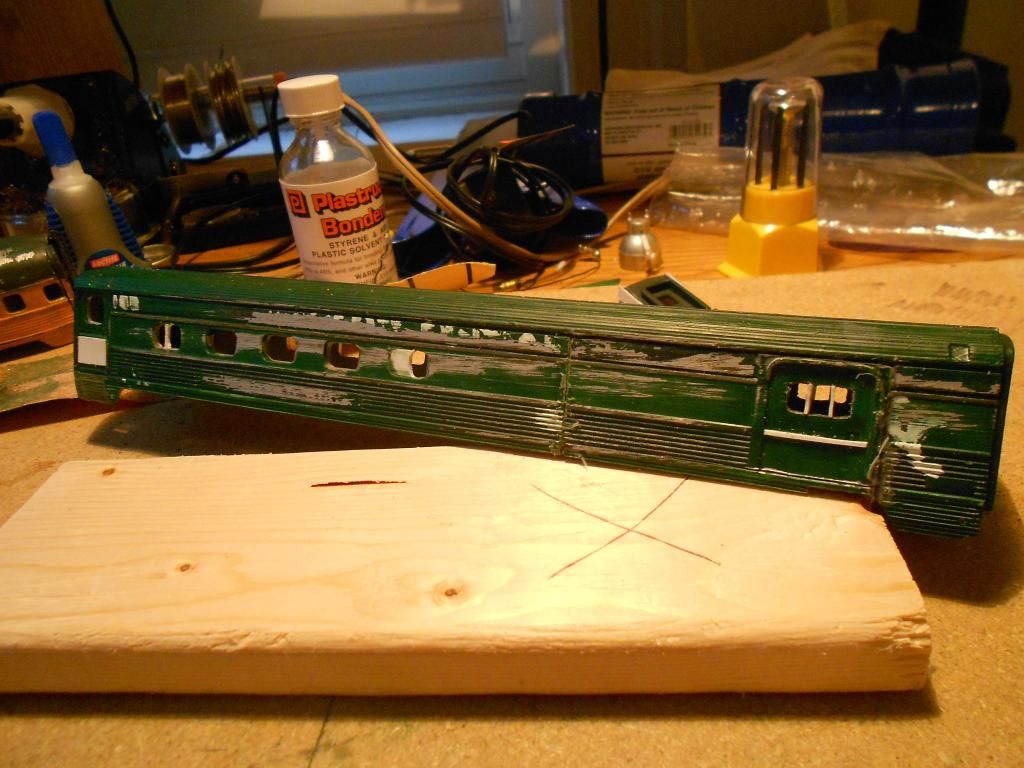
Anyway, here are a couple of short passenger car bodies I’m modifying. The first is a Mantua combine-- decorated in slime green (why did I think that was a good idea??) with sloppy painted lettering. I moved the baggage doors forward to the leading edge of the car, and used styrene to modify the windows and siding of the door.
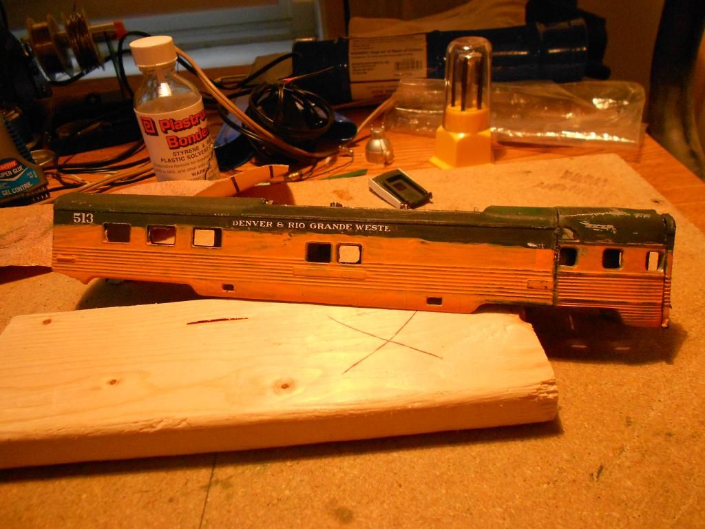
The other one is a Life-Like domed car I’m changing to look more like the ex-observation cars DRGW modified so they could be used mid-train. So far, I’ve just slapped the rounded end of a Mantua onto the end of the Life-Like car (I ran out of putty and haven’t sanded the corrugation, so it’s VERY rough-looking right now) and plan to re-attach the door thinned from the cut-off end. More spectacular pre-teen paint work!:
Besides getting these Frankencars underway, I started work on my third locomotive, the Class I runner interacting with the two smaller SLC locos. I took the chassis and drivers of my IHC 4-6-2, removed its open-frame motor and fitted a flywheel can motor an
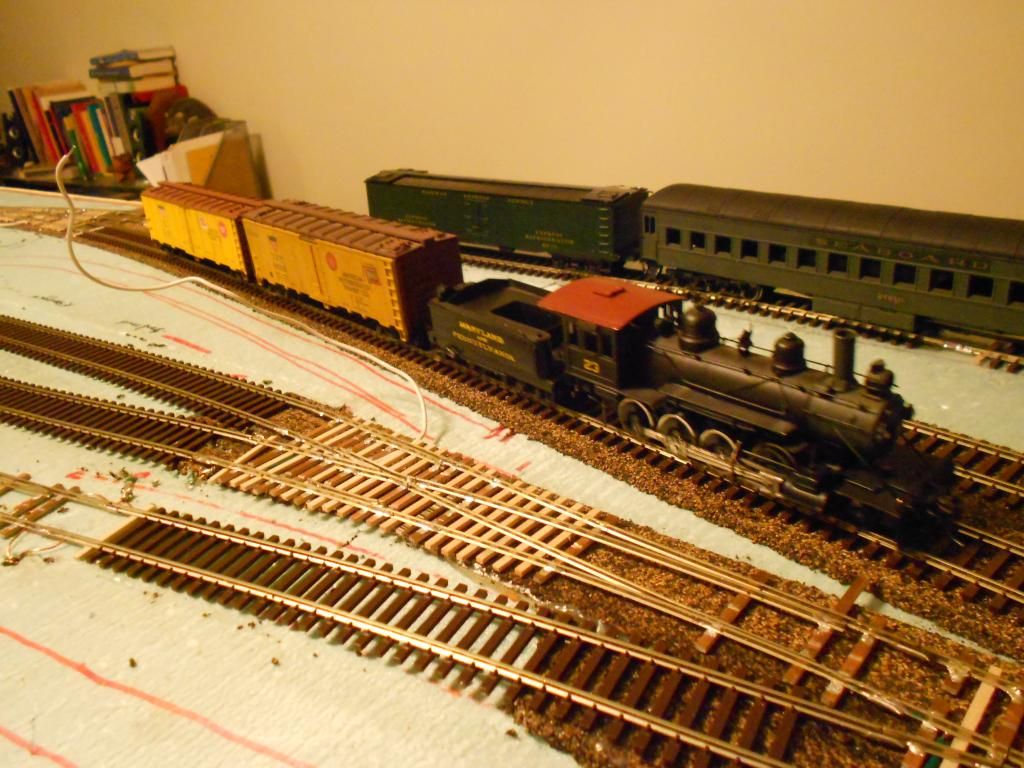
Though the turnouts are neither wired nor throwable, though the power pack is attached with alligator clips, though there are no cassettes yet for switching out rolling stock, though there is really little there except track and wire… I have trains running for the first time in nearly fourteen years!
I set up three of my four sections, used the scrap yard area for a bit of interchange staging, and shuttled some cars around with my little PFM 2-8-0 for an hour, moving in empties to the freighthouse and storehouse spurs.
Next step is to put ground throws on the turnouts and wire up the ones with longer frogs so I don’t have to nudge my switcher each time it rolls over one (which is really hard to do when you’re holding a turnout or two open with your fingers!) More rolling stock upgrading and tinkering, too, of course.
I love it! I’ve never owned a brass locomotive before. I like working on it and trying to fine-tune the mechanism. I remotored this one with a Mabuchi FF-180PH can because the open frame was so loud. Now it’s much quieter, though it’s EXTREMELY sensitive to voltage-- a beautiful slow runner, but if I nudge the controller over 25 it starts to take off like a rocket! The new pack is an MRC Tech 4 220-- I needed something with far less aggressive pulse than the 2500. It does put out 18 volts to the track-- though neither the Bachmann switcher nor the 4-6-2 is nearly as sensitive to that.
Maybe I’ll add a little more weight, too. The can motor is lighter, which may partly explain why it’s stalling over the dead frogs-- only one of them is actually as long as the loco’s wheelbase. I’m looking forward to detailing it and repainting/redecaling-- then it will truly be special.
When you add weight, be sure to add it to both the front and rear. The balance point should be at the main driver (where the main rod attaches), or just a bit forward of that point. Sometimes you can get some weight under the cab roof. If the point of balance is wrong, you could defeat the whole point of adding the weight in the first place.
When you add weight, be sure to add it to both the front and rear. The balance point should be at the main driver (where the main rod attaches), or just a bit forward of that point. Sometimes you can get some weight under the cab roof. If the point of balance is wrong, you could defeat the whole point of adding the weight in the first place.