I’ve recently upgraded several of my passenger trains to NOS Spectrum cars w/ interior lighting. Problem is, the lights flicker constantly - I keep my track clean enough that my locos don’t have stalling problems, but these cars require a whole other level, apparently, that just isn’t realistic.
I’ve heard of newer (more expensive) passenger cars that come factory equipped w/ capacitor-driven constant lighting setups, so my question is this:
Can such a system be retrofitted to an older car w/ simple (incandescent, I’m assuming?) interior lights? Could it be as simple as soldering an appropriate capacitor (and resistor?) into the lighting circuit? Looking for something that will be DCC friendly (and DC, if possible), not more than a couple/few bucks per car, and not require an EE to put together.
I figured I’m probably not the first to deal with this, so rather than reinvent the wheel, I’m asking here first.
Well capacitors would help. Replacing the lights with LEDs and capacitors would help even more. It’s a simple circuit.
Note 1: Please note in the circuit below additional resistors may be necessary before the bulb, especially if you replace it with LEDs.
Note 2: The resistor diode combination before the capacitor is to help control current surge. But if you only have a few cars, it shouldn’t be necessary.
Note 3: I use a full bridge rectifier here for potential led installation and use of a polar cap. But 14.25VDCC-1.4V rectifier = ~12.8V DC. This should be fine for a 12V/14V bulb with no additional resistor. For a standard 3.3Volt White led I would use a 1 kOhm resistor right before the LED, but you can go down to ~500 Ohm if you want brighter.
since there is always track voltage with DCC, there should be no need for capacitors nor bridge.
A single resistor and LED will work. Some people are concerned with the reverse voltage. But this can be addressed with a second diode or LED wired across the first LED with opposite polarity. Since multiple LEDs, at least two might be needed in a passenger car, there shouldn’t be a problem. Wire half in with one polarity and the other half reversed.
I have to respectfully disagree. There is always track voltage, but there’s the messy issue of pickup from the track to the interior of the car. A momentary droput will flicker the lights. The capacitor stores energy to keep the lights on (for a short interval) until power comes back. Since DCC alternates polarity and a capacitor does not, a bridge is necessary.
I think you’ll get better performance, though, by improving the pickup. Some cars have only 2-wheel pickup on each side, which isn’t enough. If you can get full pickup from all the wheels, that will do more good than trying to add electronics.
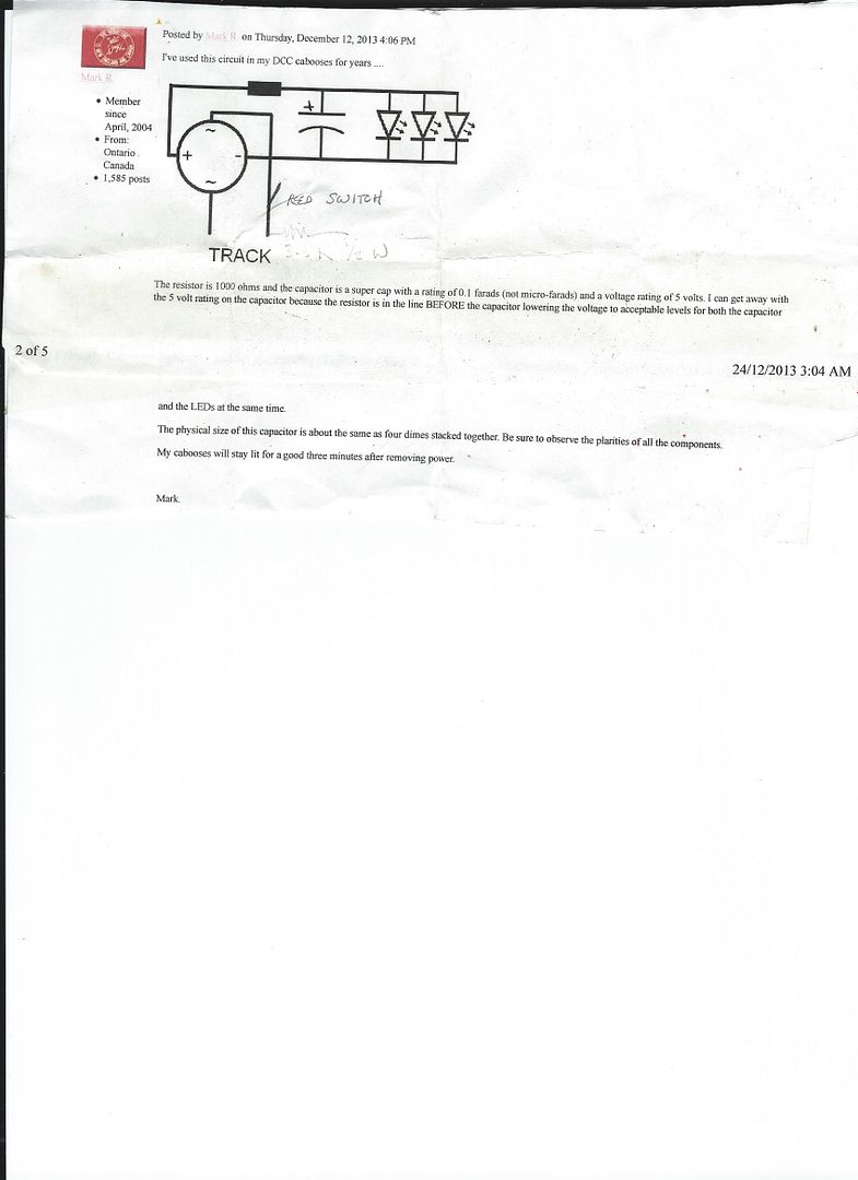
Here is another constant lighting circuit that I have used in my cabooses. It was designed by Mark R. You might consider changing the capacitor to one that is rated for 25 volts just to be safe, but Mark has used the circuit as shown for years without any problems:
I fought the flickering issue for years before I cured it permanently. Most guys on this forum will criticize my fix but I’m very happy and would do it over again.
First I finally made the jump from incandescent lighting to LEDs, I didn’t really want to go in that direction but it has worked out very good. I found out that the trick for good LED lighting is 8 wide angle LEDs per car running at super low current for even lighting (total of 2ma to 3ma at 4 volts per car).
Next I tried several different types of “keep alive” circuits, none satisfied me. My fix was an onboard rechargeable battery. That worked without any flickering, problem solved . . . . NOT! Now I had to keep the battery charged and needed a way to turn on and off the lighting to prevent dead batteries.
I solved the on off problem using magnetic latching reed switches glued under the roof of each car. The next problem was kee
Online DCC companies sell lighting kits with stay alive. Some come with a decoder also. You can control lighting. Litchfield Station is one I just looked at.
I agree that capacitors can be useful to handle problems with intermittent contact. I had assume they were being suggested for the typical reason of filtering an AC voltage.
But adding a capacitor is a bit complicated. A resistor is needed to prevent inrush current from exceeding the current limit to the capacitor and a diode across that resistor to draw current from the capacitor when there is no track voltage.
Also, there is still no need for a bridge. A capacitor will still charge with a half-wave rectified voltage.
In the schematic posted by hon30critter, the capacitor will only charge to the diode voltage and the resistor both limits the inrush current and the LED current. Also the lights won’t be on until the capacitor has a chance to charge.
In the following schematic, a capactor is added. In series with it is a resistor to limit the inrush current and a diode to provide a path to the LEDs when the track voltage drops. The diode top left half-wave rectifies the track voltage. The capcitor charges to the track voltages (~14V).
--- D> ----------------
         |        |   |
       -----      R   R
       |   |      |   |
       |   ^     LED LED
       R   D      |   |
       |   |      |   |
       -----      |   |
         |        |   |
         C        |   |
         |        |   |
-----------------------
If you are going to use a capacitor, definitely recommend going with a 25 volt variety if using a single cap… My track voltage measured at 13.8 volts, so I figured a 16 volt cap “should” be adequate. After about five minutes of operation, the capacitor destroyed itself like a fire cracker sending shards of paper and yellow shmutz through-out the interior of the car, which was not fun to clean up. I re-installed the same circuit using a 25 volt cap and it’s still working three years later …
That all depends on how much current you need. A 25V, 200uF would be a good place to start for a couple LEDs. That’s the same size capacitor that comes with a number of sound decoders. If you want them on a full minute after power goes off, you’ll need a couple super caps wired in series.
Eliminating flickering is the same as stay alive for decoders. You want to keep operating power for a short time when DCC is interrupted.
Generally, more capacitance, more time but that depends on load current. Don’t forget, a diode and 100 ohm resistor are usually parts of the equation.
This is where a general knowledge of basic electronics helps.
Some 1000 ufd, some like super caps. Generally lighting not as much. Some people like to experiment.
You could start with 250ufd and work up. LED’s don’t require the current that most light bulbs require. Over the years I have seen sufficient LED light at about 9ma.
SoundTraxx uses 250ufd for the sound part of their decoders.
I think the plunge into DCC and its general intolerance towards ‘minor’ issues and shorts is going to require me to up my knowledge of electronics bsaics, to be sure.
I understand most, but not all, of what’s been posted above and the different circuits - so I’ve definitely got some food for thought. Which is why I posted, so thanks all!
I will say hon30critter has the better circuit. Mine is more geared towards very large caps with lots of cars hooked up a similar way. But if you don’t need that much backup power, then hon30critters circuit will work wonders.
Just to give credit where credit is due, the circuit I posted was designed by Mark R., not me. Also, I believe that Mark now recommends a 25 volt capacitor as I suggested.
Yes, don’t even think about using less than a 25V rated cap for DCC track powered stuff. Even if you are absolutely sure your track voltage is only 14V - still too close to 16V for comfort with a 16V cap, and peaks and spikes will easily exceed 15V. 25V rating should be safe. If the cap is downstream of a 5V voltage regulator - then you can use 10V or 16V caps.
Actually, no … not with that circuit. That capacitor is a 5 volt supercap and the resistor is limiting the voltage / current to both the capacitor and the LEDs. The theorists claim that it shouldn’t work correctly, but they’ve been working for years on MY layout ! The key is the physical size of the 5 volt super cap - MUCH smaller than a typical 25 volt electrolytic capacitor rated at 100,000 mfd. !
If you want to use a more tradition type, then this circuit is the standard …
THIS capacitor should be rated at no less than 25 volts. The resistor value would be 100 ohms. A bridge rectifier is required where track power comes in to make sure the capacitor always sees the correct polarity. This circuit would attach in parallel to the lighting in your car. The resistor required for your LEDs would be the same as you calculate for track voltage minus 1.4 volts. The downside to this circuit is the capacitor is physically much larger than a supercap … which may or may not be an important factor.