Hi all. I’m looking for what I call a terminal block or terminal strip or distribution block, but I keep seeing the word “barrier” in product names and I’m not sure what that means. In some of these, the screws appear to be electrically connected in pairs, but I’m not sure. It’s hard to see and they often don’t describe how the connections among screws run.
Reason I ask: I have a pair of bus wires for my tortoises. The bus runs around the layout and in several places picks up a bunch of wires from multiple reversing four-post ON/ON switches. As I’ve added switches the wiring has gotten cluttered. I want to put a distro block under the layout in these areas so I can keep the wires from the switches tidy as they join the bus (the wires from the Tortoises go directly to the switches).
So what I need is to interrupt the bus with a long block with 8 or 12 poles, with a positive and negative running through end to end, but otherwise with connections only among the poles along the long sides. But it looks like many products have metal connectors between the screws in each pair. That is to say, if the block were a Viking longship with two oarsmen on each bench, the two rowers would be touching each other. Can’t have that. But I don’t really know how to specify what I want in searches.
What are some of the favorites you all use? And more importantly, what should I avoid? I’m leary of the “barrier strips” but who knows? That may be exactly what I need. I don’t want to spend money on electrical equipment that isn’t the right item for the job.
The example is a two-position, but they make them with more positions so you don’t necessarily have to overlap jumpers to get the number of terminals you need. Just make sure you get jumpers that match your barrier strips, because they have different spacings.
For the situation you describe, I would use (and have used) barrier strips with appropriate jumpers. There’s nothing about them to be leery about.
I guess I am still too wordy. I lose people. Anyway, I still have a question. The image at your middle link, which I’ve scribbled on below, shows a block with barriers oriented 90 degrees off from what I would have expected. Instead of preventing each screw from contacting its neighbor along the long axis, I would be wanting to prevent each screw from making contact with its pair-buddy. They should all be connected along the long axis anyway, unless I’m misunderstanding this animal. What I want to do is this:
…but these screw pairs appear to be connected by metal bars under their heads. And I’m not completely certain that the bus lines I’ve drawn here (thicker ink) have any place to attach here, or even that they would connect all the way through. Does this make my quandary a little more clear?
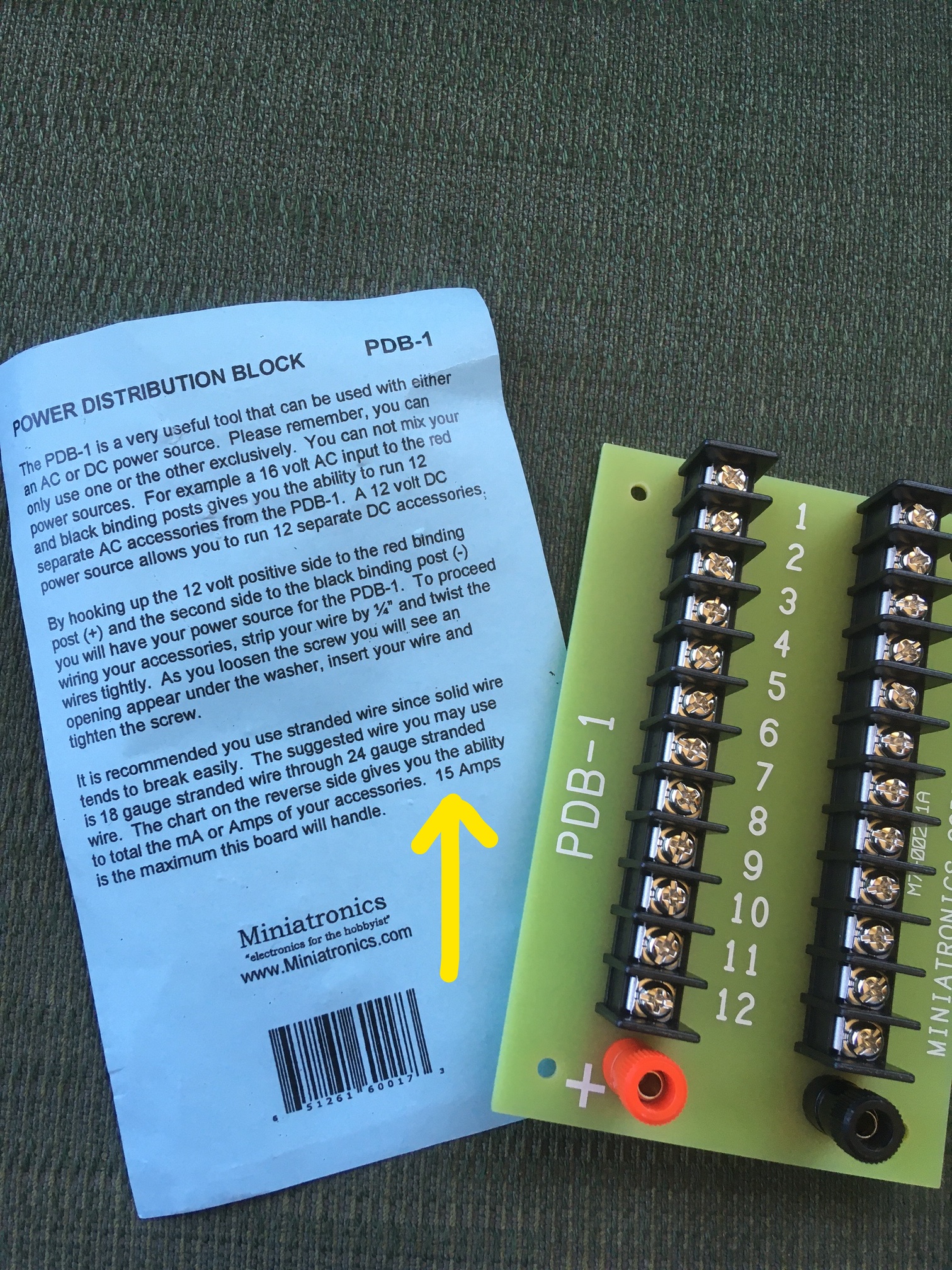
This is what I bought last year. It was exactly the right thing, electronically, to wire my layout for nearly a dozen DC blocks, but it was gigantic and it cost around 30 clams.
I was hoping to find something cheaper and smaller. But at least I understand this beast. The significant “barrier” here is the complete spatial separation of the two rows.
Charles, thanks for the suggestion. I actually started with a mix of suitcase connectors and a similar three-hole unit that you stick the wire ends into and they don’t come out. But I have a whole bunch of ON/ON switches coming into the bus in one small area, so I was having to chop up the bus line and insert the connectors on increasingly shorter wires. It is because of this clutter of connectors that I decided I wanted to use a block of some kind instead.
Mel, thanks. I may be thick, but I don’t understand how either of your photos shows an analogous situation. Those strips appear to have only a single conducting row. I can’t draw an analogy from that.
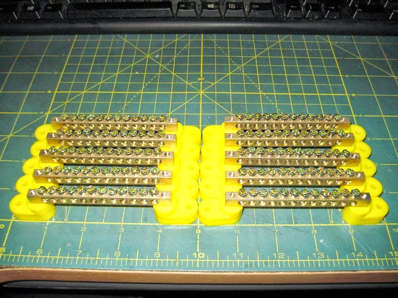
The terminal strip you pictured has two rows or two busses. I use two buss bars, two buss bars is a bunch cheaper than the one you bought.
One buss bar for positive and one buss bar for negative. The buss bars have 12 screw terminals paralleled and each hole will accommodate a bunch of wires easily.
Yes, there is a metal bar under the screw heads, and what it does is connect each screw head to its mate.
I think what might be confusing you is that you show a black and red feeder going to the strip. If you take the black feeder and connect it to the first screw on the bottom left of the strip, and then jumper between the other bottom screws on the strip, then all the outputs at the top of the strip will be the same (black) polarity.
Now get another strip and set it up the same way, except connect the red wire to the bottom left screw on the new strip. Now all the outputs at the top of the strip will be the same (red) polarity.
Actually with the way you show the strips jumpered you can connect the input wire to any of the bottom screws and everything at the top will be the same polarity.
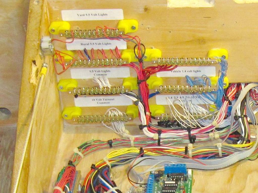
The buss bars in my control panel are mostly for accessory power. I don’t run buss wiring on my layout, every accessory has a home run to my control panel.
I have 5 voltages on my layout one of which is 1.4 volts, to prevent blowing the 1.5 volt micro bulbs accidentally I run a separate common for the low voltage so there are two common buss bars.
The buss bars shown in my picture are + 1.4 VDC & -1.4 VDC, +4.5 VDC, +5 VDC, +8.5 VDC, +12 VDC and ground or common. The 1.4 V supply is isolated from ground or a floating common.
The buss bar bottom left is 18 VAC common for turnout machines.
I have 98 pairs of vehicle headlight wires that terminate in the 1.4 V buss bars with room to spare. I use TELCO #24 solid twisted blue/white wire for my headlight lighting.
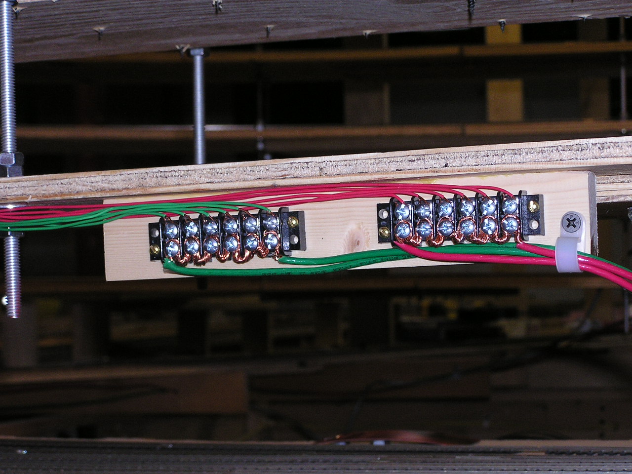
Here’s a clean-ish way to do what you’re talking about using barrier strips:
I used these to power the track on my behemoth helix on an earlier version of my layout.
The green and red are color-coded with red for one rail and green for the other. The heavy stranded wires at the bottom feed through the terminal strips, wrapping around each post on the bottom. This provides continuous power for the top posts of the strips without breaking the main conductor on the bottom.
The top wires fed different levels of the helix - one set of feeders for each level.
I could have done the same thing using one 12 position barrier strip. The connectors MrMe linked to in his post accomplish the same things as my wire wrapped around each post. I did it this way because I didn’t have the connector links.
On my current lyout I use the connector links, though there’re a bit hard to see under the spade connectors in this shot:
I used one ten-position barrier strip for two different busses here, rather than four two-position strips.
Thanks Mark, those photos are helpful. I see that you’ve done exactly what I’m talking about but you’ve sort of divided the pizza the other way, so to speak, so that all the pepperonis are on one half and the green bell peppers are all on the other half. But it works out the same.
I notice that there are not dedicated intake screws for the bus wires, you just used the end screws.
While I have several places where I use terminal strips, barrier strips or distribution blocks 95% of my Tortoise wiring is terminated with simple wire nuts. They’re good enough for house wiring they’re good enough for me.
Here’s one assortment of connection devices I use.
The terminal block in the lower left seems to be much smaller that the one you show plus the wire releases with a push of the button (using a flat-bladed screw driver makes it easier) and I don’t recall they were $30/ea.
there are quite a few choices available at various cost.
i believe the 2 most common are the black barrier strips with the exposed screws and the white terminal strips where you shove the wire into the hole. these can easily be screwed into benchwork.
i’ve had to wire them on 3’ wide panels filled with them. i’ve had problems with the (white) connectors that have the hole for wire because it’s difficult to see that the wire is under the plate that the screw clamps the wire under.
i believe it is less difficult with the exposed screw black barrier strip type because you can easily see when the wire is secure
Since some posters have posted yard sale shots of various ‘terminal’ blocks and ‘barrier’ strips, I thought I might as well include a shot of one of my under-layout panel boards. Don’t be disturbed by the image, it isn’t as cluttered as it looks [:-^]
I’ve used several different types of connectors, many of which have been recommended and described earlier. But one type that wasn’t mentioned is what I use for the two SE8C (signal) boards and one BDL168 (block detection) board. These are third-party after-market breakout boards. They are the big green PCBs that take up the majority of available room on the plywood panel, and they make making the dozens of connections a lot easier.
The two small vertical black barrier strips at the bottom of the photo use a red rooster comb connector as a kind of manifold buss with one input wire spread to feed multiple output wires.
The two larger vertical black barrier strips on the left edge are for one-to-one pass-thru connections of the 18 AWG wires from the breakout board to the 12 AWG track feeder busses that go from about 10 feet up to about 40 feet in length and are run under the layout following the actual track rails above (more or less). Each black wire is for a specific detection block.
The other wires are just wires fabricatred from various stuff on hand and supply power or control to turnouts, signal heads, and pushbuttons and whatnot.
Not sure this is of any particular use, but I just wanted to show that the OP is not alone trying to address this (confusing) issue.