I wanted to learn a bit more about these 4-wheel cars and came across a very old thread here which cited poor running qualities (hunting) and derailing, which, among other reasons, led to the demise of these cars. A question begs: How is it that the Europeans have been successfully running 4-wheel rolling stock at up to 75mph for many years?
European don’t run what in the US are considered TRAINS. Most European freights are 2500 feet or less and less than 2000 tons and thereby don’t develop anywhere near the intrain forces that typical US trains of 9000-15000 feet in length and 6000-14000 tons in weight.
The TTOX 4 wheel cars have been restricted from operation on Class 1’s for a decade or more.
there were 2 series of these cars. One with UIC suspension and one with NACO designed suspension . As I recall the UIC (European design) was the poorer performing.
Remember the Trains article some time ago (or was is Classic Trains) on the GM-EMD Voyager spines for single containers on only four wheels. They had the supspension problems solved, apparently, and trials in revenuse service on the CP gave no track or handling problems. Economics were against it, however, with even single-level two-containers on a single car being more economical, and then came double stacking.
In developing a low-cost modern “Birney” streetcar, this is the suspension ssytem I would choose. And I figured out how it could be “low-Floor” as well with the wheels protruding into the car bdy under back-back fixed seats.
As I don’t have time to post much this morning, I will start by pointing you at this introductory article on a piece of significant railroad history and then follow up by finding the papers Wickens wrote on vehicle stability. Those sources alone will answer most of the real question you’re asking.
Mr. Klepper might find that the significant elements giving the design high-speed stability can be applied to low-floor streetcar construction with only a little additional interior accommodation… with some care about introducing NVH into the passenger compartment.
I have to wonder if the buffers used on many/most European railroad cars are a factor. I would think they would help prevent crabbing and hunting, as the train is essentially one articulated unit. Short of extremely sharp curves or a defective buffer, each car is square to the next…
This is one of those places, like the lack of equalization in much British locomotive suspension, where what looks like an adequate amount of design turns out grossly inadequate in practice. (Some of this, I believe, is covered by Wickens, and Professor Milenkovic can give you a far better explanation than I can.)
The spring buffers are fine, as far as they go, and the principle is reasonable: the buffers take the place of the logs used to keep the DeWitt Clinton’s train from run-in and run-out shocks, and the chain and turnbuckle arrangement compresses the buffers so there is never uncontrolled slack. But (as with the deflicted Reading 2-10-0 truck-centering arrangement) there is little or no actual damping in the buffers – and the British ‘waggons’ have a very short length and wheelbase, so they yaw remarkably badly. Of course, their suspensions, built to the lowest price, have little inherent damping either. I am assuming that ‘crabbing’ means the same as nosing or yaw, and ‘hunting’ means the usual combination of (dynamically) coupled nosing and rolling. Once you have excited a critical resonance in one or more of those waggons, which may in no small part be influenced by the spring rate in the buffers, you shouldn’t be surprised to see it extend right up to the limits of buffer travel, even if the coupling has been drawn up so far as to ‘bottom’ the inside buffers on a tight curve.
This is just about the opposite of ‘articulation’ where the end of the forward car steers an intermediate axle
I recall seeing the Front Runner cars on CSX trains through Alexandria VA in the 1990s.There were never that many of them, and I’m not sure what advantage they were supposed to provide. My understanding was that with the introduction of 53 ft containers, their use became even more restricted.
I saw two types of car, one with a pedestal coil spring suspension (a little like the suspension units on Dash 9 and later GE locomotives) which I uderstood was a US design, and the other had a design from British Rail, the so-called “Taperlite” wich used two long plate springs of varying thickness bowed in opposite directions around a spacer above the axlebox. There was a vertical damper in line with the axlebox.
I picked up an HO scale model of one of these (at a sale) and I think only the BR style suspension was available. Assuming the model is accurate I might be able to make more comments when I’ve looked at it.
British Rail tried hard to find a future for four wheel vehicles. However, the 140 series of “railbuses” left a lot to be desired. Their operation on jointed rail led to the name “Nodding Donkeys”.
In the early 1950s, BR built a number of four wheel baggage cars for parcels traffic. For some reason twenty were built for train ferry traffic with standard UIC suspension for four wheel wagons. So they had a far better suspension design than the hundreds of others built for use at passenger train speeds in the UK. I just can’t understand why nobody in authority asked why…
Today of course double trucks are standard even in the UK. Maybe they could get knuckle couplers adopted there in time. All long distance passenger cars had them from 1951 or so, but retaining retractable buffers for coupling to locomotives.
M636C
Here is a useful page that shows some of the suspension variants and explains a bit about them. Note in particular the pictures of the Taperlite arrangement.
One of the LEV railbuses is actually preserved in the United States (albeit in shameful condition) and was apparently capable of 100mph operation on contemporary (early 1980s) American track, although the idea of rather spartan railbus service didn’t catch on at the time. The suspension fitted to this might be interesting to study up close.
I don’t have hard information on the ‘American’ FrontRunner suspension design (other than that it doesn’t seem to have worked too well in actual service) - I don’t know whether it was worse loaded or empty, or whether the characteristics of contemporary kinds of LWR helped upset its dynamics, and would like to find out in detail.
TTX referred to the European suspension as a UIC design. The North American was a NACO (National Castings). As I recall the stated advantage of the cars was lighter tare weight.
Anyway I should be with a retired TTX rolling stock engineer next Friday, I’ll pick his brain.
Thank you for reminding me about ABC-Naco.
When you pick his brains, I think what you’ll find is that they used UNItruck II suspension, which was derived from the single-axle articulated hopper suspension of 1965. (Interestingly, it seems the Axle Motion III was derived from this approach, extended to a more conventional two-axle ‘bogie’)
I don’t have my notes from ‘back then’ (around the millennium; seems like almost yesterday!) but will look and see if I can find some diagrams.
Out of curiosity, is “plate spring” a different name for “leaf spring” (i.e. two countries separated by a common language) or does it have connotations of having significant differences from a leaf spring? Either way, I did note that a fair amount of effort went into ensuring the axle would remain perpendicular to the axis of the car.
On four wheel street cars, an effort was made to have the spring support for the car bodies attach close to the ends of the bodies to minimize nodding. The sharp curves on street railway trackage limited wheelbase to 7 - 8 feet, which doesn’t appear to be a problem for freight cars.
Car donated to National Museum of Transport Kirkwood, MO

Actually, you need to read your Wickens. The idea is to be sure that the axle RETURNS to perpendicular after small deflections, and is able to move laterally with increasing compliance but then is returned to center with a minimum of overshoot and very good shock absorption.
I found it interesting that the later ‘cost-effective’ versions of this suspension did, in fact, keep the perpendicularity of the axle more defined, while providing if anything even more lateral damping and shock absorption (see the pictures for HSFV-3 in particular). I suspect this may have something to do with British permanent-way characteristics, especially on track maintained for high-speed passenger traffic.
Look carefully at the distal ends of the radius rods on HSFV-1. If those were intended to hold relatively precise perpendicularity (as in the case of radius rods with ‘silentbloc’ ends between bolster and sideframe of a pivoting truck) they would be implemented in solid elastomer. Here you have paired springs (with damping in the middle). When you look at the diagrams of wheel-rail interaction much of the reason for the arrangement will be much clearer (and it is explained in pretty good English besides!)
Looking at the blown-up Naco suspension on that car at MOT, I note that one of the lateral guide plates on the near axle seems to have fractured off, and something similar may have occurred on the far end. There surely had to be some enhanced mechanism of lateral compliance (other than through twist in the spring nests) and some potent lateral damping, but I sure don’t see it from the picture. Now I will have to go up to MOT and do some careful measurement and photography to figure this out, and see if there are patent numbers on some of the castings…
My understanding is that a ‘plate spring’ is a single leaf, and it is normally loaded at the ends (a good example being the suspension spring in a pendulum clock) and not like a half-elliptic spring like the ones in the Taperlite arrangement.
That may, of course, be an excessively academic understanding. Here is a closeup of a Taperlite spring setup:
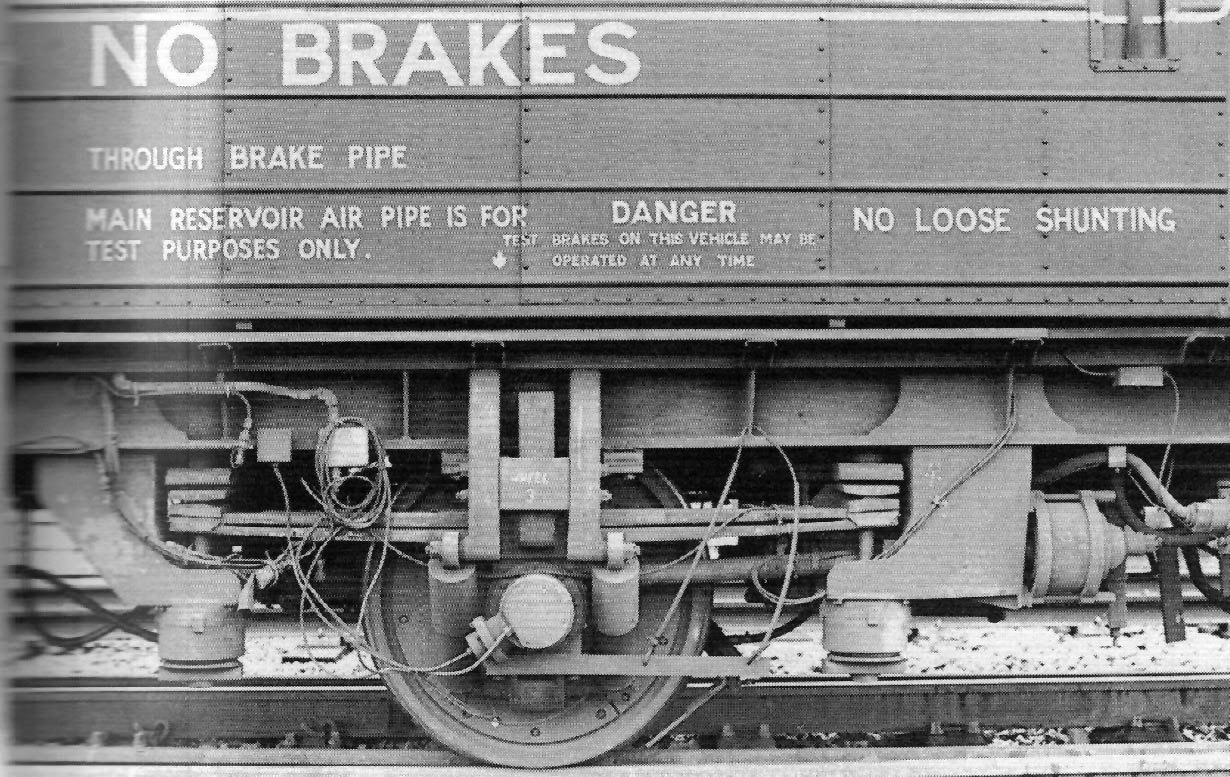
which shows that the spring is essentially two parallel leaves rather than the progressive, length-graded nest of leaves that a typical leaf spring has. Note that, as with axles using the early B&O continuous structural spring between axleboxes, or the Winans ‘friction wheel’ there are NO BRAKES and in fact tread brakes on the pictured setup would need to be paired and act precisely across the center of the wheel (as with Reichsbahn driver brakes) in order not to derange the suspension action. Note also what I believe is a tubular radius rod, which is what allows the ends of the Taperlite springs to be suspended as they are, with only relatively thin plate connecting spring ends across the carbody. It is hard to make out the ‘bottoms’ of the large canted dampers, but they bear on the very bottom of the axlebox assembly, providing vertical, lateral, and roll damping.
I remember the Winans leaf spring truck from White’s freight car book, doubt if you can do much better in reducing the weight of a 4 wheel truck.
As for brakes on the two axle bobber, place a disk brake on the center of the axle, with the calipers on a forked radius rod, where the forked ends are connected to bearing on the axle and the “rod” end connected towards the center of the car. Dunno how well this would work…
I do see the angled dampers. It also looks like the ends of the Taperlite spring may be held longitudinally and laterally in place by vertical rods.
The “plate spring” does make a bit of sense.
Works real well – in fact if you look at the picture you will see that already installed on the wheelset (see the cheek plates screwed to the wheel center?) This is part of the ‘tribology train’ that braked the wheel under experimental control to test adhesion.
I am a very strong believer in these side-acting “disc” brake setups (as found on the AEM-7s and similar electric locomotives for effective use from the highest speeds). The only problem was that, if you thought the Wickens long-radius-rod setup was too expensive for British four-wheel waggons, how could you justify the cost of the plates, brackets, shoes, and other components needed to implement this kind of brake?
Here is a picture of a different Taperlite setup that shows the way the disc brake was implemented on some of the test cars:
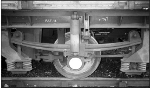
This also shows just how wibbly the actual hangers from the ends of the Taperlite spring to the stuff connecting it to the car could be. I defy you to use the word “held” in conjunction with that setup: it seems to me to be free to deflect in just about any plane to a significant amount, with (again) the torque rod actually locating the axle relative to the car frame. (Again, it can be helpful to see exactly how the hangers in an Ohio truck have their ends arranged, and what they actually link to, to see what their designers thought they were controlling and why … and why kludged rigid sideplates might have had to be stuck on after the fact when things were a bit too flexible in operation.
I think this was the “production” arrangement and the more complex setup on RDB 999900 was associated with the Tribology testing.
Certainly the simpler arrangement was that used on the Front Runner if I recall it correctly.
Since there were only ten of these in the UK, I assume the Front Runners were the nmost common vehicles eq equipped with this type of suspension.
I used the term Plate for the springs rather than Leaf because I’ve always assumed that leaf springs required multiple plates, and the Taperlite with two plates of variable thickness didn’t qualify for that name, although I don’t feel strongly about it either way.
M636C
As a further resource for those of you who are interested in the subject, here is a PDF download to a review of many freight-truck designs circa 2002.
The ABC-NACO single axle suspension appears to be covered in 7.1-7.2
(A perhaps interesting aside: Fig 7.5 has both what I’d consider a ‘leaf’ spring and a ‘plate’ spring, as defined for this discussion, in the same picture…)
There is nothing as good as a trip down memory lane…
I tested the first of the Scales radial trucks in 1977. In fact I visted Brian Scales in Pittsburgh that year, and we saw the trucks under construction. They were intended to use standard AAR springs in order that replacements would be readily available. About the only other detail was that the trucks were painted light green. The other anecdote is that when the first pair were out on the road, we found that they reacted differently. While one steered correctly, the other didn’t. We found that th