I will be using a 12V red LED with a TCS FL4 “light-only” decoder. The FL4s have 12V output, if I understand the description correctly from the TCS website. Like operating a 12V incandescent at a lower voltage to make it look more realistic and last longer, would it still wise to add a small value resistor to lower the intensity of the beam?
There is no such thing as a 12 volt LED - it either has an internal or external resistor to allow that 2.2 volt LED operate on 12 volts. That being the case, the resistance chosen will no doubt be calculated to operate that LED at its full potential on 12 volts.
You don’t need to add any more resistance, unless … it is too bright for your liking, or you plan on living longer than the LED itself ! [swg]
most LEDs range from 2.2 volt [red] to 3.2 volt [white], and already include resistors to operate at twelve volts … they also -usually- are operated at maximum brigtness as well [-usually- 20 milliamp] … i would recommend adding extra resistors to reduce brightness, but that’s just what i prefer …
Thanks, Mark. I seem to recollect reading that here on the forum at some point.
Do different color LEDs operate at slightly different voltages? I’ll find out on Monday whether the LEDs come with internal or external resistors. I’m guessing internal.
Sounds like the instructions were written by Microsoft? "In order to use light dimming the Constant Bright Light for this dim lighting adjustment to work?
From Windows: "to shut your computer down, click Start button ".
From what I have seen the past few years here and other forums, most seem to like to operate LED’s at about fifty percent or about 9ma using a 1k resistor.
Super bright LED’s require a lot more resistance. If I was concerned I would grab a five k pot and do some measuring. Not a big deal. This is not rocket science.
I do recall reading in this forum a couple years ago there is a company that sells LED’s with a built in resistor. Probably more than one company now.
The reason for the question is that I installed my programmed FL4 decoder in my Aerotrain observation car but it immediately blew out the red LED taillight. (The white LED is working fine.) I replaced it with another [deep] red LED that I purchased at Micro Center. It lasted…maybe a minute but it also burned out.
The PCB board that provides the interior lighting for the observation car and connects to the rear taillights has two (2) 2K SMD resistors; one for each taillight. I double-checked them with my Fluke meter and they are working properly. I also disconnected the F0F & F0R wires from the PCB board so that the FL4 decoder would be completely isolated from the Loksound Select that operates the locomotive before testing them out. And the red LED tailight worked with no issues when it was connected to the Loksound Select.
As mentioned, the rear white F0R taillight is working just like it’s supposed to. The red LED, OTOH, stays on constantly, will not flash, and eventually burns out. I tested the same F0R function with a yelo-glo LED. It doesn’t burn out but it also won’t flash when I press F6 and stays on all the time.
I’m going to put the observation car on the programming track tomorrow a
I recently bought some tri color LEDs, three individual LEDs in one package. I’m using them for searchlight signal heads. I balanced the brightness of the three colors as close as I could by eye, Red at 2.2ma, Green at 4.0ma and Amber at 12.5ma. The different colors draw a different amount of current for equal brightness.
while the white would be a 3 volt part, and would have a nine volt drop…
the red led would only be a two volt part, with a ten volt drop … a 2k resistor -should- give only a 5 millamp illumination , well within the safety rating …
if you have a multimeter, it may be a good idea to check the resistor value, and the actual voltage applied to the led/resistor combination …
As mentioned in my earlier response that Mel quoted from, I did double-check each of the 2K SMD resistors with my Fluke meter and they were working properly. (1.996V, to be exact) I also took your suggestion and measured the voltage across the red LED leads (that I currently have a white LED connected to) and got 2.524V.
Out of curiosity, I removed the black heat shrink from around the bulb of the old red tailight LED and it looked just like a regular white LED. Then I had my Homer Simpson moment…“Wait a minute! Isn’t the color of the left lens on the back of the observation car red??? DOH!! [banghead] - Yes, it is!” [D)]
Okay, so both taillight LEDs are white and the 2K SMD resistors are illuminating them at ~2.5V. Wish I had discovered this before ordering the red LEDs. [:(] No bother. They weren’t that expensive ($0.45 ea) so I’ll find another use for them.
This still doesn’t explain why the currently installed white LED for the red lens remains illuminated and doesn’t respond when F0F is deactivated on the FL2 decoder. (AUX 1 & 2 are twisted together and was programmed for gyralight when pressing F6 and constant light when pressing F5; neither of which work.) As mentioned, I’ll place the observaton car on the programming track and see if the values for AUX 1 & 2 has changed.
It also doesn’t explain why the original white LED for the red lens bur
Factory circuit boards - now you see why I just rip them out and hard wire most of the time.
Perhaps there’s a trace that needs to be cut - otherwise the 2K resistor is not actually in the circuit. Why one LED would go through the resistor and the other doesn’t in out of the box configuration is unusual but in my experience with factory boards that are supposedly “DCC ready” or can be made “dcc ready”, I can’t say I’m completely surprised something’s not quite right.
Since the car length PCB also illuminates the interior of the observation car with three 0402 SMD LEDs, I want to keep it in place. And both rear taillights worked fine with when used with just the Loksound Select.
I removed the white & yellow wires going to the F0F and F0R pads of the PCB that lead back to the Loksound Select in the locomotive. That leaves on power (red & black), common (blue), and VO+ & VO-; the latter they use for the interior lighting using green & purple wires.
Because that’s the identical wire colors used for AUX 1 & 2 of the FL4 decoder, I thought that that might be where the short laid. However, I used the Fluke meter to confirm that those are not connected at all to the F0F & F0R pads. The manufacturer in China used most of the correct color-coding for the observation car. The exceptions were the aforementioned purple & green wires and an orange wire traced to the F0R pad. Strange because they used yellow for the wire going to the F0R LED. [:S]
We’ll I’m completely stumped. It doesn’t seem to matter what wires I connect or disconnect: The F0F taillight will NOT flash and stays on all the time in FWD or REV. The only thing that it does do is brighten and dim when I press F5. [:S]
F0R flashes the gyralight in REV and constant when F5 is activated - just like it’s programmed to. I rechecked the CVs in Decoder Pro and even recopied them back to the FL4 decoder (in the event I missed something) but still no change.
Here’s the current top view of the observation car PCB labeled:
Left: F0F, F0R, and the common(+) are disconnected from pad
Right: COM FL4 wire from FL4 (decoder) is soldered behind COM F0F 2K SMD resistor and COM F0F & F0R wires soldered to separate pads.
Before the above, I wired the FL4 decoder to the LEDs in the following configurations, with the left COM wire (P7) soldered to the pad:
COM FL4 and COM F0F wires soldered to COM F0F pad
COM FL4 and COM F0F wires soldered to COM F0R pad
COM FL4 wire soldered to COM F0F wire with isolated 2K resistor in-between
COM FL4 wire soldered to COM F0F & F0R wires with isolated 2K resistor in-between
In each case the F0R LED worked flawlessly and the F0F LED never matched the programming of the F0R LED.
Wondering if I did something to AUX 1 & 2 of the FL4 decoder in scenarios #1 & #2 because COM FL4 bypassed the PCBs 2K SMD resistors? Is it worth starting over with another FL4 decoder and trying it again? The programming worked just fine on my testing platform.
It’s possible, if the resistor was bypassed and the LED blew, it could take the function output with it.
Are the interior lights just connected tot he track so they are on all the time? if so, are both sides of those lights completely independent of the two lights for the rear of the car you are trying to control with the decoder?
That’s what I was wondering, Randy. When I initially tested the LED with the FL4 decoder wired in, the F0F LED was on a split-second then went out. No big flash; just on then immediately off.
Why would the LED still illuminate if the function blew? Or, did it only partially blow?
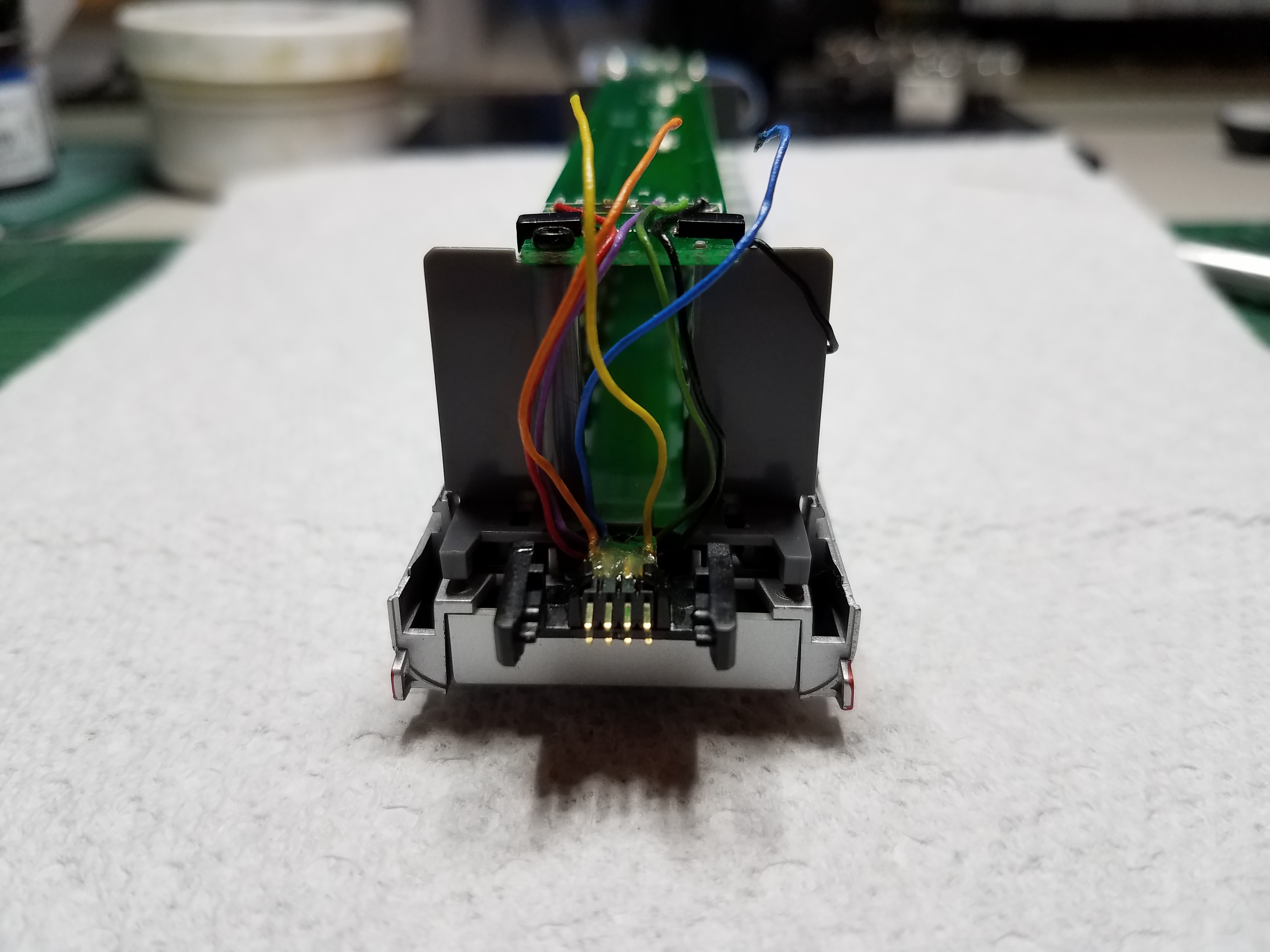
No, the interior lighting on each car comes on when the car is physically connected to the car in front of it. There’s a male & female 4 x 2 mini-connector that makes the connection:
One car end has the male; the other end, the female and both connectors swivel freely to accommodate even tight curves. Magnets on the diaphragms keep the car snapped together. It’s a neat design.
Because the green & purple wires on the left side of the circuit board were the same colors as AUX 1 & 2 of the FL4 decoder, I traced and ohmed them from the pads and they are not connected to the F0F & F0R pads on the upper right side of the board that the FL4 decoder is connected to. They power the 0402 SMD LEDs that light the interior and are protected with 300-ohm SMD resistors.
With the original wiring, the Loksound Select operated the rear taillights of the observation car and only illuminated if the car was p
Quite likely that could cause some sort of sneak path for current to flow between the decoders, possibly a bad thing crossing power districts, too. If there are connections for the tail lights through the inter-car connection (which there have to be, otherwise they would not work off a decoder located in the loco), you should completely isolated that to put a self-contained decoder in the trailing car. It’s OK to keep track power through the whole train, the more pickup the better and the less flicker - or need for a keep alive. Self contained is nice, but when in operation, if other pickups can be added in parallel it would be a bonus.
I looked on Con-Cor to see if they had any more info, but there’s not much about adding your own decoder to these things. There was however a note that says it is pretty easy to connect the electrical connections between cars incorrectly, most obvious symptom being the rear lights don’t work right. Which makes me winder if getting the connector off when putting the train together doesn’t end up feeding track voltage into one of the function wires, which is definitely bad. The article also makes it sound that there are some diodes somewhere in all this (or the LEDs, red and white, are hooked up anti-parallel) because it says the red light is on in forward and the white light is on in reverse as it comes out of the box. But all the decoder references are for the version with the Digitrax sound decoder.
I’ve found if the cars are not fully engaged, that will cause the observation car taillights not to illuminate - even if the interior lights are illuminated. But you make a valid point, Randy.
The red (left) & white (right) taillights come on in FWD & REV, respectively - no matter what decoder you use. (On the prototype, the red taillight was only used when traveling forward.) Both taillight LEDs are white but are differentiated from one another by the red (vs clear) lens built into the rear end of the observation car.
I ordered another FL4 decoder from Litchfield Station. Should arrive Thursday so I’ll have a chance to program it and try it again this coming weekend. What an adventure - just to get a rear taillight to blink. [%-)]
OK, wait, the rear lights switch no matter what decoder is in place? Hmm, they HAVE to be hooked fo F0F and F0R in the decoder to do that on DCC< on DC, they just have to be wired across the track anti-parallel, so one lights when the direction switch is one way, and the other lights with it switched the other. Or there could be some more sophisticated circuitry for constant lighting and such.
While you may not want to remove the factory board because it also handles the interior lighting, I would suggest totally disconnectd the rear LEDs fromt he board and adding your own resistors, keeping them 100% isolated from the factory board - there’s something going on there if they can be controlled by the decoder up front, and while it’s perfectly OK to connect 2 or more function wires from the same decoder to the same LED, connecting a function wire from one decoder to the function wire of another is probably a bad idea for several reasons. If you’re really pressed for space you could probably slice through the traces to either side of the 2K resistors and scrape off the solder mask and use those as your resistors instead of installing 2 more, just be sure the traces are completely cut and the resistors are in no way connected to any other part of the interior lighting circuit.
SHould be easy enough to test the old FL4 to see if the function is blown, connect it to a test track and reset it so all functions are simple on/off. With all of them off, there should eb 0 volts from the function wire to blue. With it on, somewhere around 12 volts. Sometimes they fail on - so no matter wha the state of the function is, voltage is always present. In your case of using 2 outputs to the one LED to be able to have it both steady on or flashing, if the steady on output is blown and always on, that will kill any chance of flashing.
Even if it is blown, TCS should send you a new one, goof proof warranty and all, even if it was your fault, first replacement is on