I am in the process of wiring lights on my control panel to show polarity on the different blocks on the layout.
The approach I am taking right now is to solder a wire on the track on one block (let’s call it A) and solder the other wire on the adjoining block on the same side of track ( let’s call that B). So when a train is in block A heading to block B and the light is on I know I need to change the polarity in block B.
Here is the problem I have come up with -
Using a multimeter I notice that the range of volts going through the track when operating trains is around 3 to maybe 11 or so. With that range an incadescent at 3 volts is hardly visible.
I originially used an LED but as you pros already would have known that if I am using only one rail it would only illuminate when there is a complete circuit in one direction, not the other.
Is there another approach that I can take to accomplish my goal?
I thought about that but was hoping for a solution that uses only one color light.
I looked for a bi-color LED where both colors are the same but could not find one. Is there an LED with only one color but the current can travel in both directions and illuminate the LED?
You might use some kind of relay that is sensitive enough to trigger on low voltage but accept peak track voltage, and use it to switch a circuit that powers the LED from independent correct voltage.
There are inexpensive buck/boost cards – one very recently referenced in another thread [Just Plug System] – that I think can be set up to operate as constant-voltage supplies from variable DC source. That ought to be perfect to run a LED of choice. Someone will give you the information on these in better form than I can.
Note that a typical red/green LED inherently shows polarity: this is two light-emitting diode cores of opposite polarity in series. The diode functionality ensures only one of the two conducts when DC of either polarity is applied; the light-emitting functionality makes the diode in conduction light up. The problem here is that like a valve the color-coding shows absolute position rather than ‘what it ought to be to match what you want’. Some of the people who have wired color-light signals will have answers to setting up the logic involved in showing an appropriate ‘clear’ signal for an approaching train-in-block, which could be used as an indicator for matching the ‘approached’ polarity correctly. But unless you’re interested in signals, which I doubt, that would likely be too difficult or too expensive.
You’re better off learning how to wire the blocks so the cab automatically determines the correct polarity, which is more complicated but well worth learning.
The principal use of a bridge rectifier is to convert AC to full-wave DC, but everything he’s doing is in DC already. And his LED inherently incorporates a diode, although at restricted voltage, so four of them correctly oriented would give directly visible evidence of which diodes are forward-conducting…
That is an idea! I have been just starting to play around with buck boosters as a prelude to do some lighting on the buildings on the layout.
If I can give a nod to RR_Mel, he has been super helpful giving me advice on lighting solutions based on the way he has his own layout wired.
I’m thinking a buckbooster set at 1.5 v and have it power a 1.5v incandescent then I wouldn’t have to worry about blowing the incadescent and it would still be bright enough to see.
I am now wondering if I could wire it in such a way that one buck booster could drive multiple block wirings. Possible???
Each block is wired to a DPDT center off switch so I can change the polarity or turn each block on or off. The throttle is for motion only.
When I am operating the trains and hitting all those DPDT switches like mad I sometimes forget what the polarity of a certain block is.
I am a visual person so if I have a light on my panel on the frontier between two blocks that can illuminate to tell me that I better change the polarity of the upcoming block or I’ll get a short then I can keep the train merrily on its way.
When you have DC of unknown polarity, a bridge rectifier gives you DC of a known specific polarity out. To drive a single, non-bipolar, LED (he’s already stated he only wants one light and one color) from power with unknown polarity, you’ll need a rectifier in there somewhere.
The only problem with the rectifier is it will drop the volatge about 1.2 volts.
A diode bridge is an arrangement of four diodes in a bridge circuit configuration that provides the same polarity of output for either polarity of input.
A buck/boost converter should work. One problem is you would have to feed it with DC of a known polarity so you would have to have a bridge rectifier circiut. The bridge rectifier would drop the voltage about 1.2 volts, so the converter would have to turn on around 1.8 v. It may be hard to find one that turns on that low but still handles the maximum voltage (there are buck/boost converters that don’t have a polarity requirement, but that just means they have the rectifier on board and they will have a higher minimum input voltage to compensate).
The easiest circuit would just be a bridge rectifier feeding an LED, but again, you would have the 1.2 v drop, so the LED would have to turn on around 1.8 v. Some red LEDs do have a 1.8v forward voltage, but you would also have a large enough resistor to protect it against the maximum voltage and once you add that it may not be visible at the lower end.
The best way I can think of off hand would be to use an optocoupler (actually a pair of them or a single AC input optocoupler to handle the unknown polarity) and separate power source to drive the LED. The circuit gets a little more complicated, but it could turn on very bright at a low volatge and little variation in brightness throught the range.
I have never seen a layout wired that way, also don’t understand why you would want it that way, since it causes the very problem you are trying to solve which the “normal” method avoids.
I guess I don’t understand why its a problem, if the switches control the polarity, wouldn’t the handle of the switch indicate which polarity the track was assigned?
It seems sort of redundant to put a light over a switch to tell you which way the switch is thrown when the handle of the switch would indicate the same thing.
I’m in agreement with Greg here. Just why do you need a reversing switch on each block and not in the throttle?
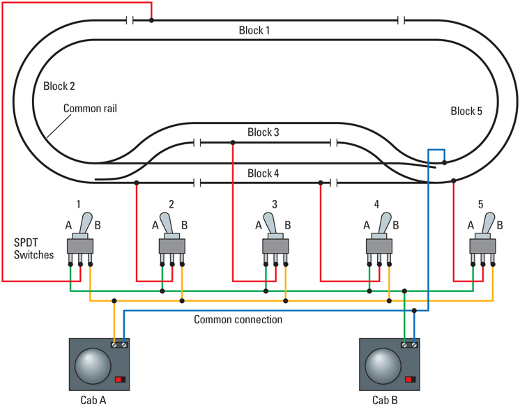
Kalmbach Diagram
There’s no reason to have reversing switches at 1, 2, 3, 4, or 5.
The big downside to “bridging” the gap on each rail is that whatever you bridge it with will allow some current to pass.
So if you have block 1 energized and block 2 turned off with your center-off switch, if there is a locomotive in block 2 it will be drawing current through your “lamp/diode” indicator.
A diode will allow “full” current (up to the rating of the diode) to pass in one direction which would negate any circuit interruption provided by your block switch.
If you have two diodes, “back-to-back” bridging the gap between blocks you negate the reason for having a gap in the first place.