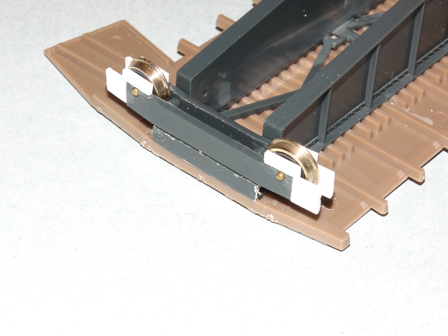
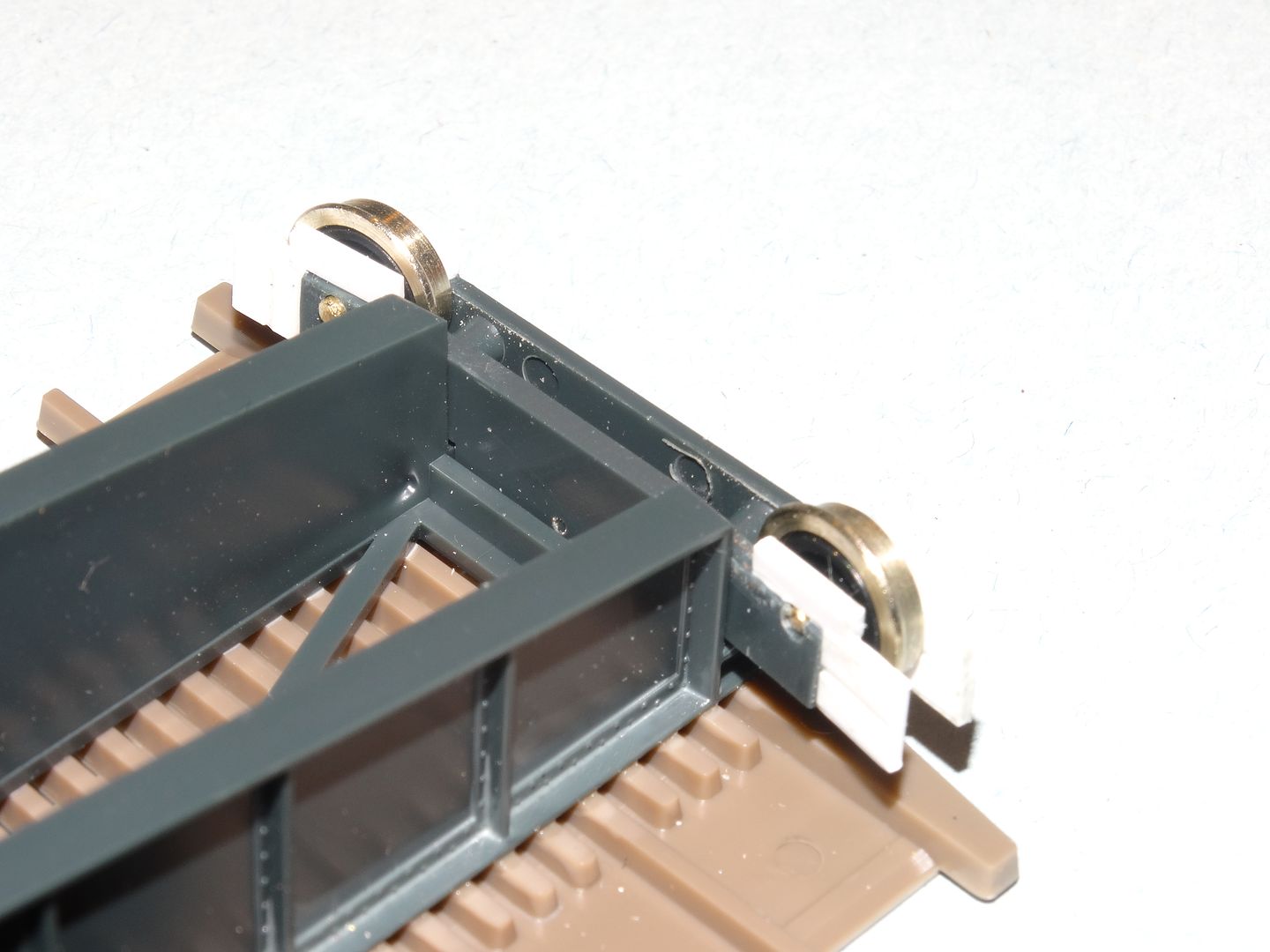
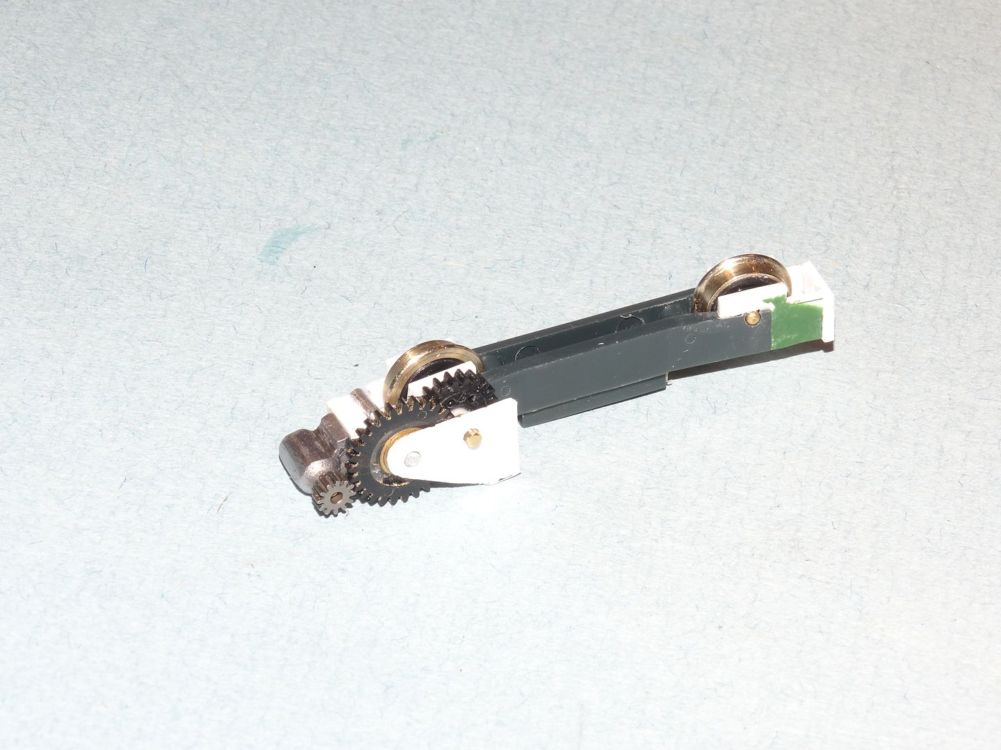
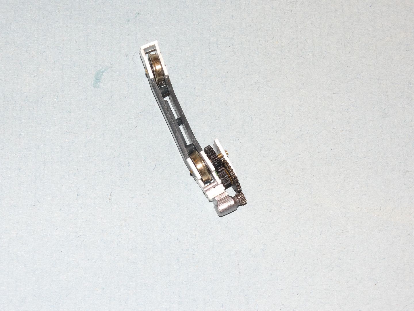
I have the revamped bridge wheel assemblies roughly assembled to see if the new wheels lined up with the pit rail. I’m happy to say that they lined up perfectly! I have to raise the bridge truck assemblies just a tad so that they aren’t lifting the bridge up. That should be fairly simple to do. Here are the modified trucks in rough form:
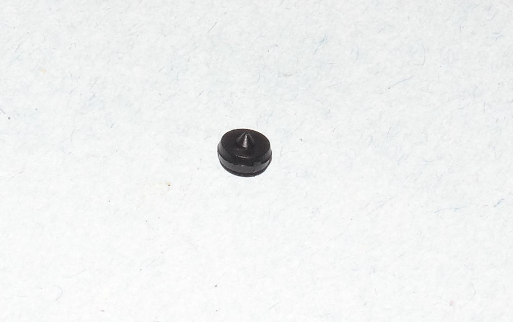
This is what the wheels supplied with the kit look like [N][+o(]:
I discovered that the bridge doesn’t rotate freely through 360 degrees. I think I can solve that problem by sanding the ends of the bridge.
I agree! Walthers always seems to take shortcuts in their mechanical designs. I had to re-engineer the bascule bridge mechanics, their walking-beam oil pumps sound like a strangled cat and the concrete rotary-kiln needed much rework. Still, 'ya work with what 'ya got…
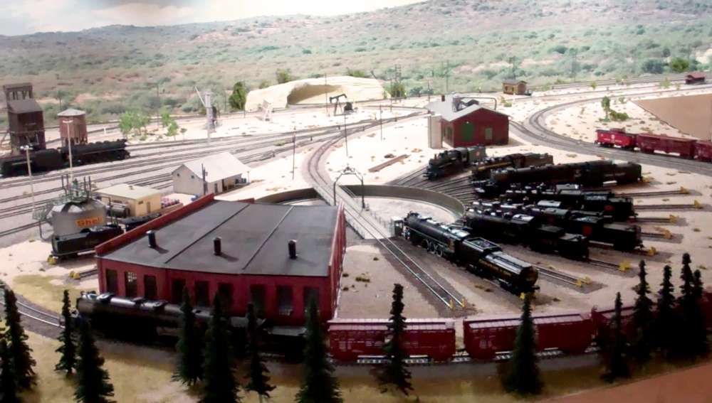
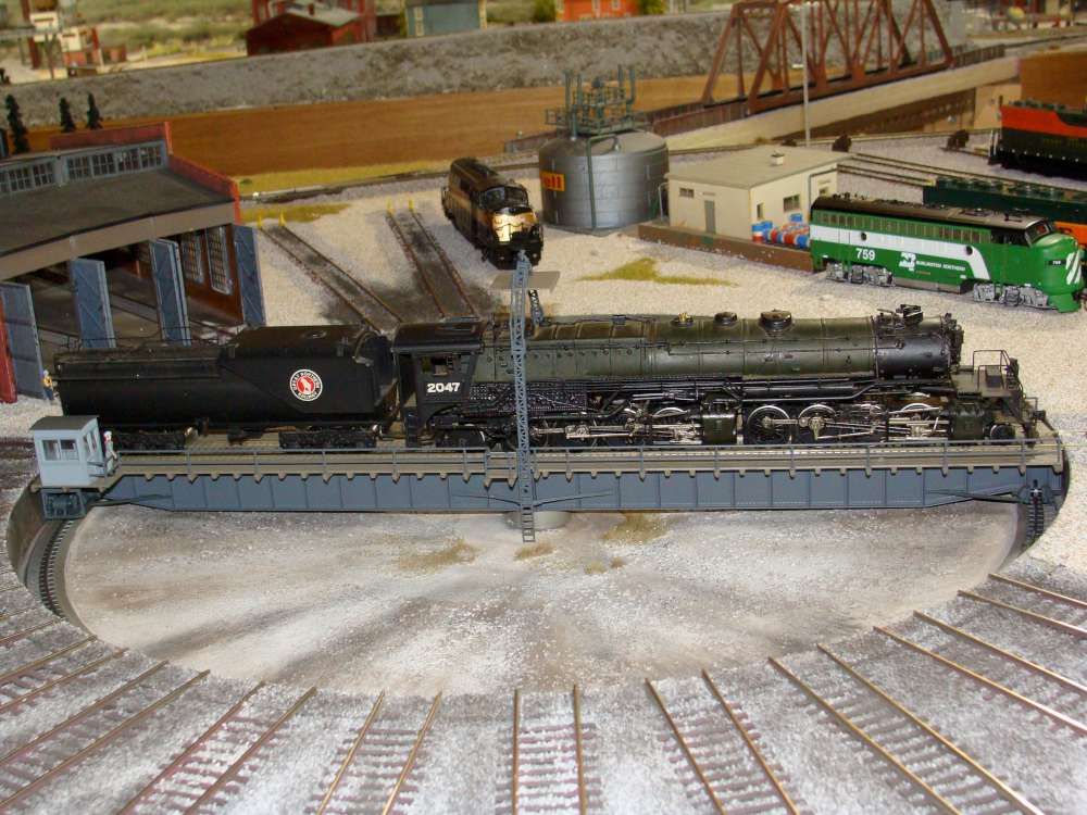
Here’s some additional pics of my Diamond Scale 130 footer. I realize that I installed this “temporarily” back in 1997 so I’m ready to get back to “dialing-up” the details but we all may fall into that “now that it’s running fine, I hate to mess with it” attitude. I’m guilty.
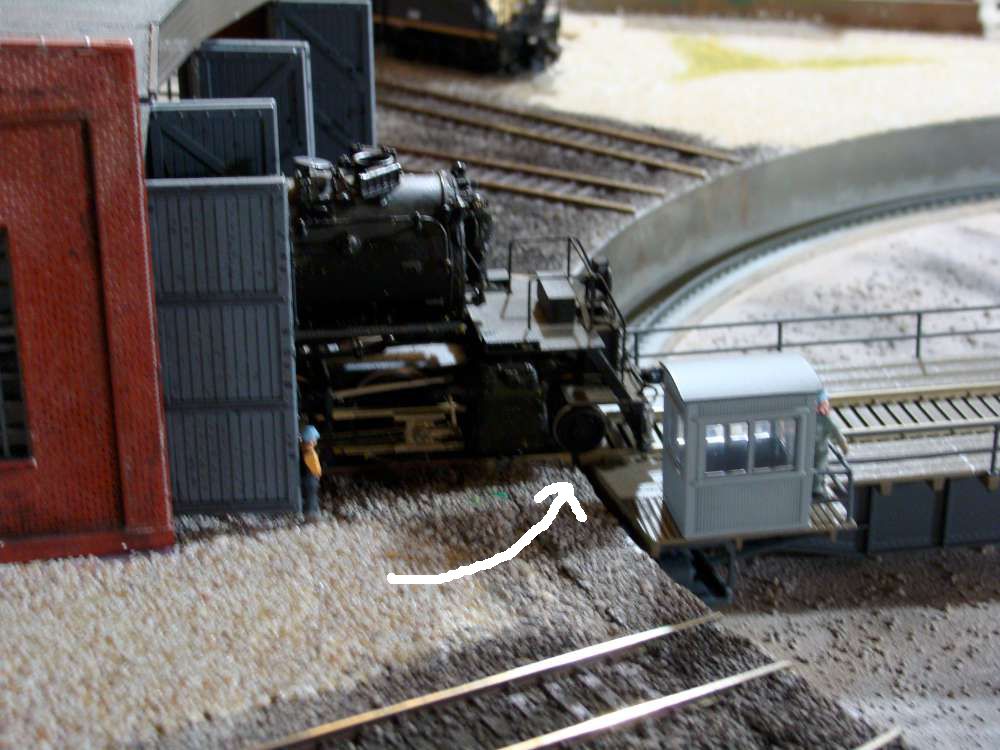
This shows the “arch” It actually carries current to one bridge rail. I never got around to making better wire connections to the “Slip-Ring” but, again, it works fine. I simply brush painted it and I see lots of bare metal. The near upright looks a little crooked but can be adjusted since it is on 1-72 brass screws to carry the power.
Operators cab. Someday, real glass will be installed [:-^]
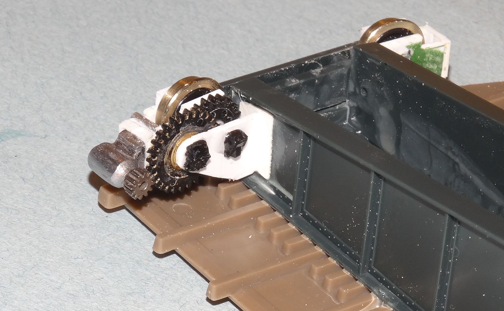
The motor and jack-shaft. Note the journal box on the pinion axle [Y]. Note, too, the nasty insect webs. As often as I brush and vacuum them away, they come back hours later!
Back when I installed the klunky Walthers lamp posts, they were “as good as it gets”
I just sent you a couple of PMs regarding your offer.
Thanks for the additional pictures! The visible drive system is really neat. I hadn’t even thought about that sort of detail. All the Walthers kit gives you is two panels that supposedly cover the motor. They’re going in the spare parts bin!
I learned, or rather, re-learned a simple lesson tonight. All the parts for the bridge trucks that I was testing were just sitting loose in place. That was fine until I turned the bridge over to look at something else. Yep, parts all over the floor! The lesson - when your are using gravity to hold things together, don’t defy it! Fortunately I was able to find them all but bending over to pick them up was a bit painful. My back has been the pits for the last few days. Whine, whine, whine…what I need is less whine and more wine!
Thanks for sharing your TT photos. Very creative construction methods!
I think I can solve the wobbly bridge problem if I can get the new bridge wheels at the right height so they will be in contact with the pit rail but not lifting the bridge up. That will require some repeated careful filing and test fitting but things are pretty close now. It looks like I only need to raise the bridge wheels buy about 1/16" to get everything to line up. If I can get it right, the bridge wheels will support the weight of the locomotive as it crosses on to the bridge.
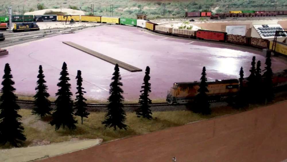
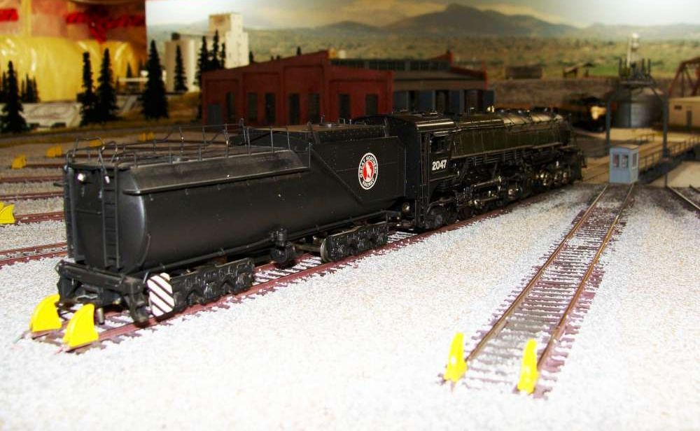
I don’t know if these picuture files will help, but here is my 130’ Walters installed some two or three years back. Never a problem. No problems with installation either. These are the units we all had to wait almost two years to arrive on backorder as the factory in China was low on production and fixing problems.
Unit runs beautifully. I use the controller instead of programming cvs for TT track assignments. This installation is much faster and far more foolproof than fiddling with cv on a throttle to use the TT.
Had left a bed of 2 in high density foam over 1/2" ply for the base. For the longest time it simply resembled a big pink lake in the layout until the unit arrived.
Finally installed.
Used CN style bumpers.
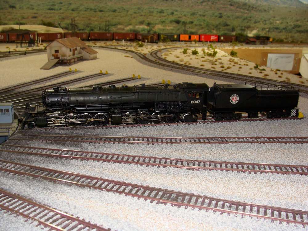
Visiting valuable brass big loco.
Worth a small fortune for this full set of GN brass collected by a friend’s father in the '60s
Who is more accurate…Brass loco or Walters round house. The loco does not fit.
The controller came with it, along with all instructions and paper templates for construction/insertion and programming. I had just one little piece out of place on the gearing of the TT motor when it arrived as I recall…a cog that had bumped out of position, and it has been fine ever since. Just once in a while a loose bit of my ground cover sand will sit on the ring gear in the pit, and just one little grain will stop the motion. But as this cover is almost never loose, that has happened only once since installed.
I have even dumped a locomotive into the pit when the locos DC settings were left active and all is well.
Tonight I did a test assembly of the bridge, pit and motor and the turntable turns almost perfectly. I say ‘almost’ because there was some very slight hesitation at one point. I think it was caused by some flash on the big gear because the bridge did not touch the pit at any point, other than the wheels of course, and they roll very smoothly. The most important part is that the bridge does not rock at all. I applied a fair amount of pressure but there was no deflection.[:D]
The drive is noisy but I think once it is buried under the layout it should be fine. I’m sure the prototypes must have made some noise too.
I have given a lot of thought to indexing it but I think I will go with the simplest system possible. I think I have two choices actually. One is to use a center off momentary switch and the other is to use a rheostat with center off position. Jogging the bridge to get final alignment would seem to be easier with the switch, but I like the ability to start the bridge rotation slowly which the rheostat would provide. I hate jerky, toy like movement.
Any thoughts? Can anybody suggest a specific rheostat?
Dave
Edit:
I have to rant a bit. Sorry.
One of the screw sockets that is used to hold the lower bushing/motor assembly broke off when I was tightening the screw. Another one has split so that it required repair too. This is a device that by nature requires assembly/disassembly/reassembly to get things lined up properly. Why would the designers not make the screw sockets more substantial? It just doesn’t make sense to me.[:(!][banghead][|(]
I spent the better part of an hour adding bearing caps to the bridge bogies. I had a lot of trouble getting a square cut while removing them from the arch bar trucks until I finally smartened up and used my coping saw. Then two of them dissappeared into the ether when they popped out of my pliers. One looks a little rough but it will be fine once painted. Keep in mind that the bridge is upside down in the picture.
Whether or not anybody will ever see them under the deck remains to be determined.
Dave
By the way, regarding the motor housing screw sockets that I was ranting about, I surrounded them in epoxy so hopefully they will be a little more solid.
I didn’t like the unpainted colour of the pit so I primed it with automotive primer in anticipation of painting it with something a bit more grey. I actually kind of like the primer colour so I may stick with that as a base.
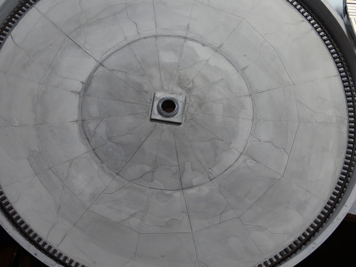
I also decided to scribe the normal stress relief seams in the concrete as well as add some cracks. I used a #11 blade to cut the lines and then used a chisel blade to remove the raised edges from the cut lines. I may have overdone it with the cracks but I can sand them down and fill them if it looks too busy. Otherwise I will just blame it on corrupt concrete suppliers! I will use a wash to bring out the lines in the concrete as well as adding some appropriate stains etc. I really like the idea of having a small pool of oily water in the bottom of the pit.
I also want to have a bit of vegetation growing in the cracks so I ordered a bunch of Woodland Scenics supplies today.
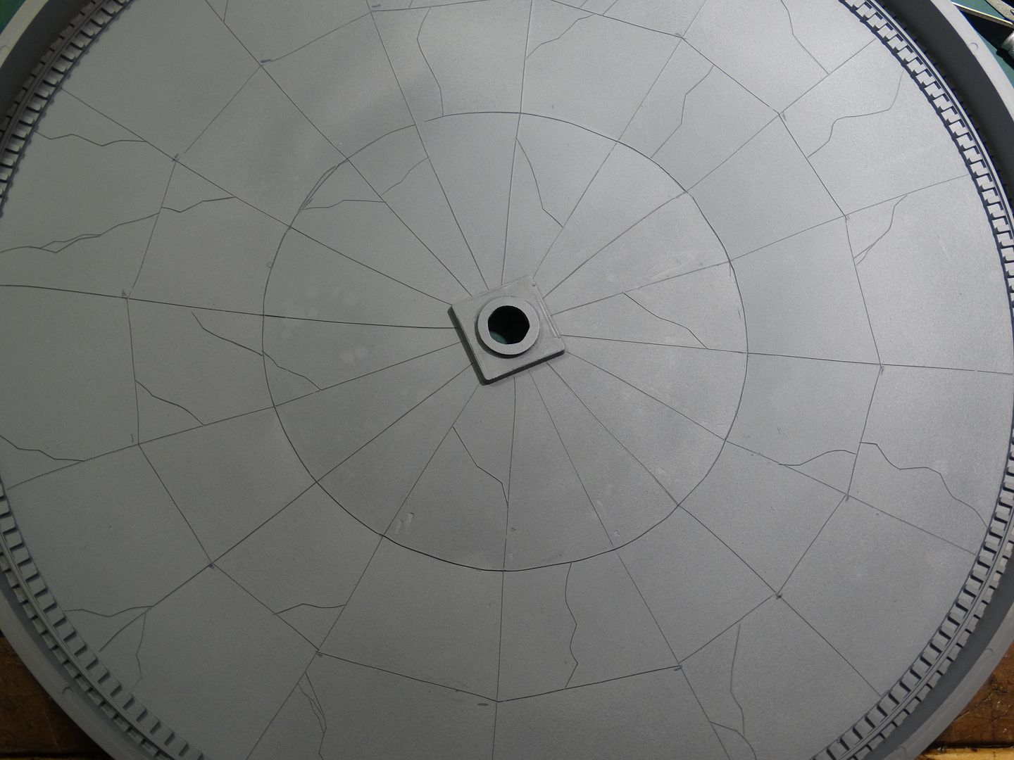
Here is the pit with the seams and cracks cut into the surface. Please tell me if you think it is overdone:
(Edit - after looking at the picture I do think that the cracks appear to be overdone but I’ll add a bit more weathering to see if I can mute the effect somewhat. If not, out comes the sandpaper!).
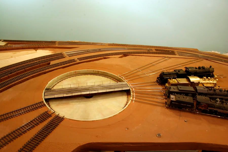
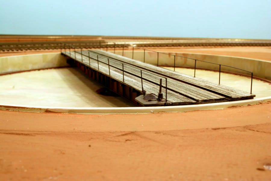
I think the weathering will mute the cracks. BTW: They look good. Here are a couple of shots of my scratchbuilt 70’ turntable. Still haven’t finsihed the ground cover, but it works well.
There is more info on the construction of this turntable on my website (see the link in my signature)
Thanks for the thumbs up on the concrete cracks. I have ordered some scenery materials to scenic it with including some self adhesive grass tufts. I’m hoping that I can cut the tufts into narrow strips so it will look like grass is growing out of the cracks in some places.
Right now I’m in the process of painting the ring rail and ties. What a tedious job!
I checked out your website. Nice job on the scratch built turntable! In fact, nice job on the whole layout!!
You have got me thinking about replacing the top of the bridge with real wood if I can’t get the appearance I want with the plastic. Unfortunately I already have the rails glued to the bridge. I had to do that to check the bridge height after I changed the bridge wheels.
Thanks for the kind words on the layout. Send me a PM if you want the current updates.
On the wood deck: you can probably glue some scale 1X stock right over the plastic with no modifications. I have done this on flat cars and it looks great without raising the original surface height very much.
Here is the other scratchbuilt TT on the layout (yeah - the vertical alignment needs to be fixed):
Nice job on the other turntable. I love the NBW castings.
I have some very thin mahogany which might work but it has two problems. One is that I’ll have to see if I can split it half lengthwise because the strips are too wide to be reasonable in HO. The other is the naturally dark colour. I want a tone similar to your bridge boards so the mahogany would have to be painted anyhow. I’m also concerned that it would be hard to get the thin strips perfectly flat.
Before doing that however, I’m going to try some paint. I gave the bridge boards a coat of medium grey this morning and I think it is a good start. I will try to paint some individual ‘boards’ a slightly different colour. I’m going to make up a cardstock mask and use my airbrush.
I used scale 1" x 12"s (not sure width) basswood from Mt Albert. These were alcohol/shoe dyed to get the color you see. Eileen’s tacky glue and some weights will keep things flat and snug while the glue dries.
The painting thing is a good idea as well. Check out Harold Huber’s technique for making plastic look like wood here -
I just finished a second Walther’s 90’ TT kit. The first one I built about 10 years ago and it runs but stutters and jumps.
I took more time with this one and it came out pretty good. Here’s what I learned:
The bogie wheels are not round. It looked like the mold halves didn’t quite line up. I filed the wheels into a better shape with a small file. After assembling the bogies in their trucks, I ran the trucks at an angle on a sheet of 600 grit sandpaper. This made the wheels turn but also scrubbed off the high spots. I applaud the skills and patience of those who retrofitted metal wheels!
The big drive gear had some flash on it, particularly where it joined the sprue.
The benchwork support must be absolutely flat and the hole for the pit must not have any spots that make for a snug fit. That causes the pit to warp slightly and causes binding.
Take time to test things. You can put the deck in the pit, attach the lower housing, and spin the turntable with your finger to see if there’s any binding. That’s how I found an area in the pit opening that needed to be enlarged. After it passes the “spin test” the motor should be the last thing installed.
As far as noise, there is a grinding sound. But the one prototype turntable I am familiar with, at the Steam Railroading Institute (operators of the Pere Marquette 1225), is not particularly quiet. There’s a good bit of noise from the drive unit. There is also no such thing as indexing. The control is a lever that obviously has contacts that give you a few speeds in each direction. It’s normal to “bump” the turntable to get it lined up - and often “bump” it back because you overshot the desired track.
I think I’m going to use a real wood overlay. I’m going to call Mount Albert Scale Lumber on Monday to order some scale 2 x 8s and 4 x 8s. One of the problems with the molded bridge planks is that whoever did the design put all of the end to end board seams on the same beam. Not a particularly strong way of doing thing, although I guess if the underlying structure was steel it wouldn’t matter too much.
I’ll post pictures once I have made some progress. The scale lumber will take a week or so to get here. In the mean time I will experiment with adding some stains to the pit and rust on the bridge.
I’m at the stage where I have the bridge turning smoothly under power. I went through most of the steps that you suggested. I took one look at the bogie wheels that came with the kit and immediately tossed them. The metal wheels seem to work very well although I had to make some modifications to the position of the bogies to get the wheels to sit on the ring rail properly. There is no wobble in the bridge.
The motor/gear noise is quite noticable but I’m hoping that once the turntable is installed in the benchwork that things will quiet down. I think one of the problems with the noise is that the pit tends to act like a big speaker cone. I may add some spray foam insulation to the outside bottom of the pit to try to quiet it down but obviously the motor housing will have to be accessible.
Getting the fit in the benchwork right is definitely important.
I’m not going to index the turntable. I think it will be much more interesting to use a manual switch, including the ‘bumping’ that you mentioned. I am actually considering using an old train set power pack so I can vary the speed of rotation.
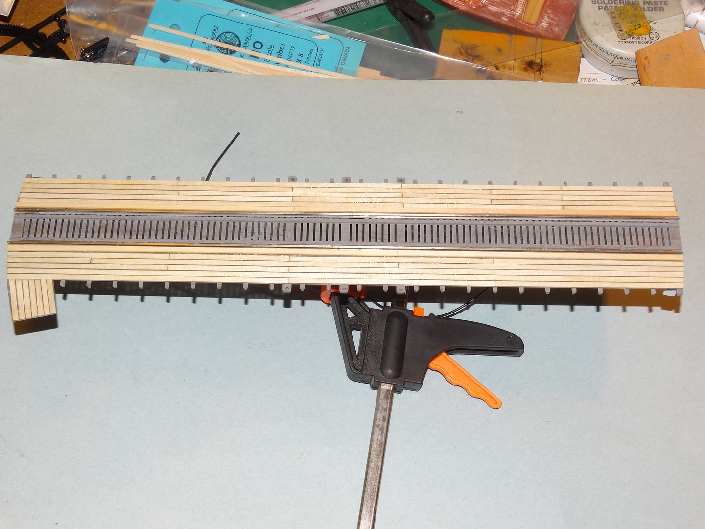
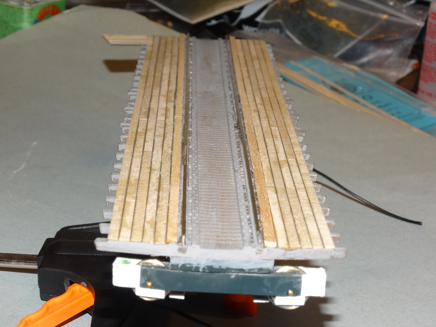
Today I received the Mt. Albert Scale Lumber boards for the bridge deck:
End view. I think the real wood planks look much better than the molded ones, but I do recognize that the grain is way out of scale. I now have to add a ton of nbw castings to the safety beams outside of the rails. I’m not sure if I will leave the area between the rails as is or cut it out and put in real wood:
A couple of days ago I applied a first layer of weathering to the pit. I’m hoping that the brush strokes and puddle lines will be less obvious when more ‘layers’ of weathering are added:
Comments welcomed as always. This is my first major attempt at weathering so please share your advice.