What is this diagram called and what do the circled numbers represent?
What is this diagram called and what do the circled numbers represent?
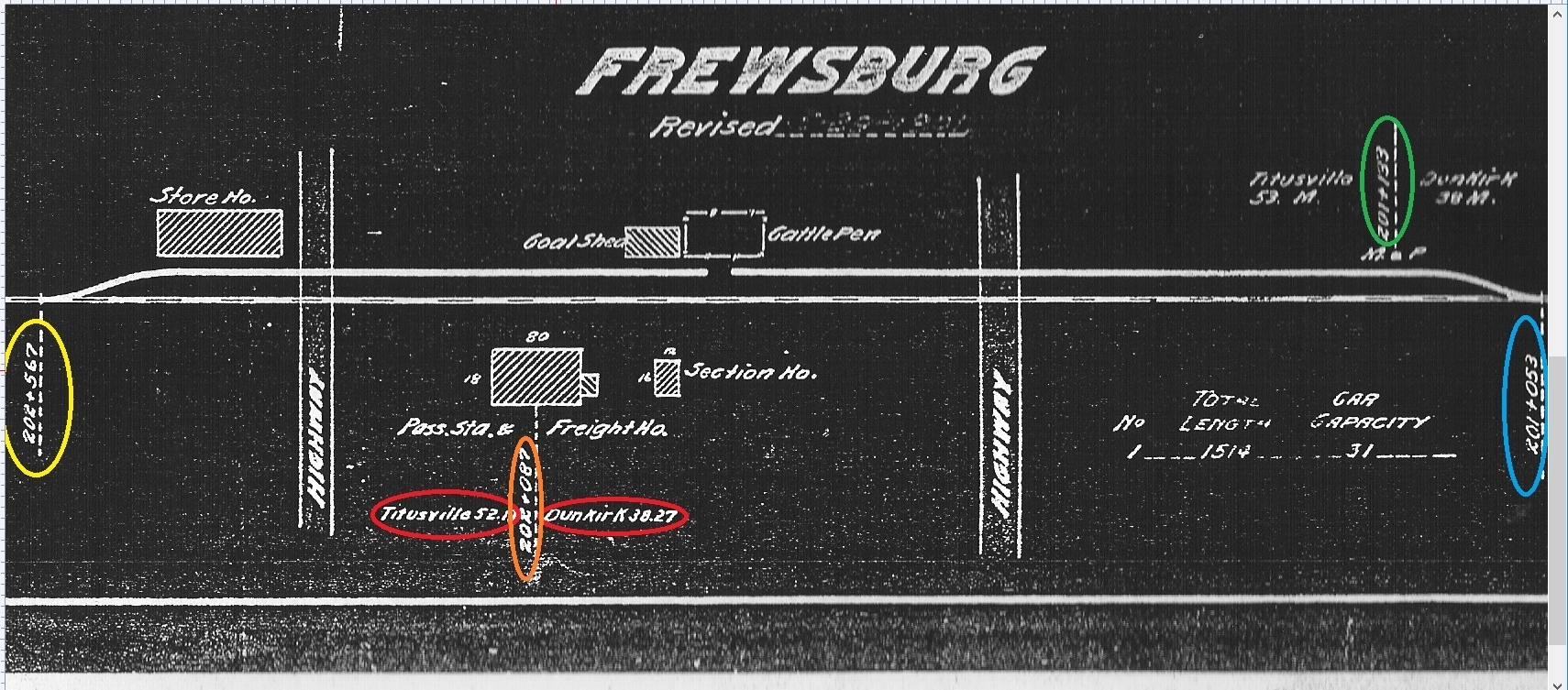
Its a track profile.
Yellow, orange, green and blue are chainage stations, the number of feet from whatever the starting point. Yellow is 202567 ft and Blue is 201053.
202567-201053 = 1514 ft
The note says the total length of the siding is 1514 ft, which is 31 cars. That means the railroad figures a car is about 45-48 ft long.
The Reds are distances in miles to the two stations, probably the begining and end of the subdivision, its roughly 38 miles to Dunkirk. Green is marked M.P., probably for “mile post” and shows 38 miles. 38 miles is 200640 ft and the footage marker is 201133, so that tells me that the start (milepost zero) is at Dunkirk.
The Dunkirk 38.27 is the mile post as is the Titusville numbers.
IIRC the other numbers is for the adjoining blueprints…
Terms used. even those by professionals for the same thing often vary.
I believe most users would call that drawing a Track Chart. A Track Profile would show vertical alignment and is often included on a track chart. Additinal infomation may also be on the Track Chart. The infomation on a Track Chart depends on the percieved needs of the railroad. I have also seen a railroad generated drawing of a cross section through railroad right of way called a Track Profile.
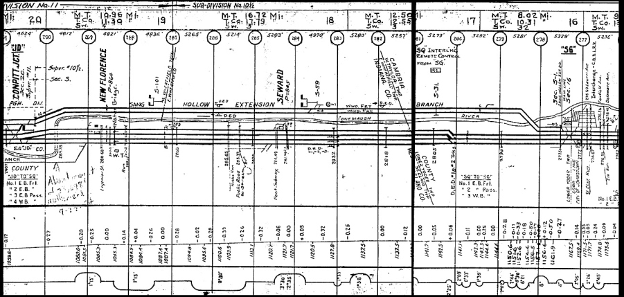
In addition to showing the tracks, this Chart has vertical alignment, curves (on the main lines) , signals, roads and streams, county lines. There are also Track Numbers and the intended use (passenger or freight).
http://tim-meyers.com/wp-content/uploads/2013/06/sg-trackchart2.jpg
I was thrown off(-track, lol) by the ‘+’ sign being used instead of a ‘,’ in the numbers. I could not image what a 3 digit no. + another 3 digit no. could mean. Now that you point out that it’s a 6 digit no. it seems almost self-evident. [:$] Thanks.
I haven’t come across any Track Profiles for the route I’m looking at for LDE’s (Erie RR’s Corry, PA - Elmra, NY) but have seen examples depicting much longer distances than that of the one you posted.
Since you did post a fairly simple one, I’d like to ask a couple of question about Track Profiles just to satisfy a curiosity I have about them. Beneath the gradiant % graph there is another graph with semi-circles with #'s that appear to be degree and minute notations.
Would those deg.min. notations be the sum of the grades shown in the Grade Chart above? (I can never quite read what they are on any of the Track Profiles I see online).
Do the semi-circles represent a curve needed to circumvent what would otherwise be a steep grade if taken more directly?
Does the direction of the semi-circle (clockwise v. counter-clockwise) indicate the direction of the curve relative to the general direction of the RoW if the curve didn’t exist? (ie. curve to the right vs. left)?
That is a common engineering notation for surveying stations.
They indicate curves. A frowny curve is a curve to the left going right to left on the map. A smiley curve is a curve to the right going from right to left. The degrees and minutes are the sharpness of the curve.
Olson - The ErieLackawanna HS store used to sell track charts on CD…
Heres the link to a CD with both valuation maps and bonus 1962 track charts from Corry Pa to Hornell NY… (Actually, Kent OH to Hornell, but for your needs…)
They have others available as well.
For those interested, this site has a good selection of track charts and other data. Mostly the Ohio area but a few other areas are there, too.
http://www.railsandtrails.com/default.htm
here are some of the track charts:
http://www.railsandtrails.com/diagrams.htm
You may have to download the “Deja-Vu” plug-in for viewing the larger resolutions but it is worthwhile.
http://windjview.sourceforge.net/
Good Luck, Ed
What you said was my “2nd guess”, lol. Thanks.
In case anyone is interested how that odd sort of notation (e.g. 201+053) came about . . .
A survey chain is 100’ long. Even if the alignment is a mile long (or 2 miles or 10 miles) it is measured 100’ at a time.
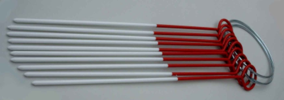
It sounds easy enough for the chaining crew to remember just how many 100-foot increments they’ve traversed, but after a few hours in the hot sun, a 100 feet here and a 100 feet there can easily be dropped. The head chainman carries a ‘quiver’ of survey pins in a spring loop on his belt. Sometimes those pins are called arrows. Here’s a photo I found online:
The head chainman starts with a loop containing 10 pins; the rear chainman starts with an empty loop. They pull the first segment and the head chainman sticks a pin in the ground. After each 100-foot segment, the rear chainman picks up the pin and puts it on his belt loop. After 1000 feet, the head chainman has an empty quiver and the rear chainman’s is full. That point is designated 1+000. They take a short break, exchange belt loops, and start the process all over again.
Educational stuff on a Sunday morning. Sorry.
Robert
While navigating through the ELHS site I dead-ended here and figured an in-person visit to the archives in Buffalo was the next step: http://www.erielackhs.org/index.php/archives/89-valmapindex
Your link helps and I will bookmark it. Thanks.
Ed, I think you posted the railsandtrails.com link in a different thread and I saved the link and have been slowly looking through that site.
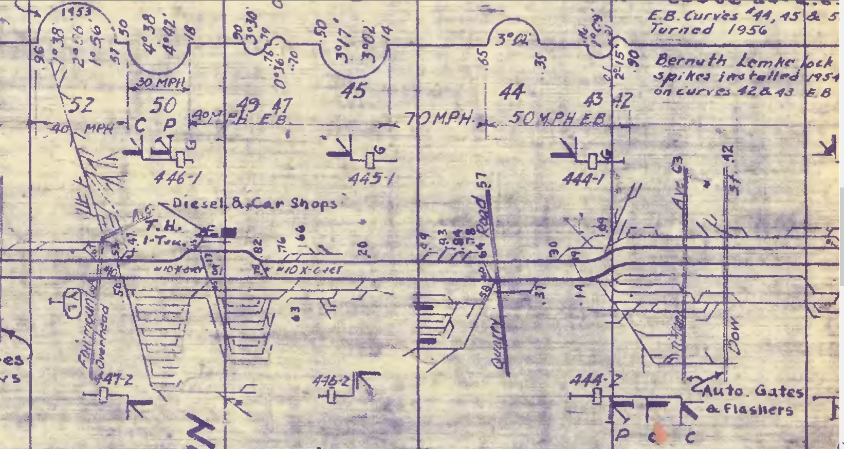
Just this morning I looked at the Erie RR “Meadville and BS&W Divisions” 1942 (rev. 1961) for the “Mainline Lakewood (NY) to Salamanca”. As a result, I’m doing a mental “happy dance” because this Track Profile includes Jamestown (NY)'s two yards posted at the top of this thread: http://cs.trains.com/mrr/f/13/t/261907.aspx
Not only that, but it gives me all the industrial trackage in the Lakewood-Jamestown-Falconer area (which is what I am most interested in modeling with greatest degree of integrity of operations). [:D] I won’t have to look at Google Earth scars and ‘ghosting’ to deduce trackage.
I love learning stuff like this. Of course, you know, I’m going to be thinking of this every time I look at a Track Plan. (Just like I imagine a knotted rope every time boat speed is discussed.)
[Edit: I came across this Google book that might be of interest to some: https://books.google.com/books?id=ZkAFAAAAMAAJ&printsec=frontcover&hl=en#v=onepage&q&f=false ]
Hey Olson-
My educational stuff was a casual-front-parlor-recreation-room kind of stuff. Your educational stuff is actual, legitimate, hard-core sort of stuff. Here I am, forty years out of college, and I still occasionally wake up in a cold sweat worried that I forgot to do my homework assignment or something. [8-|]
Thanks for the memories.
Robert
Funny. I’m 25 yrs. out of college and I occassionally miss having an algebra or trigonometry homework assignment. I still debate re-taking Pre-Calculus (for the third time) so I can get that ‘W’ (withdraw) and lone ‘F’ off my transcript. Well, not “off” but notated with a subsequent passing grade.
Robert.
While your description of the use of chaining pins is indeed accurate, I have a correction. A surveyor’s, or Gunter’s chain is 66 feet long divided into 100 equal length links. Most original railway alignments were laid out using these Gunter’s chains. It wasn’t until about the turn of the 20th century that steel tapes of 100’, 200’, and 300’ lengths came into wide spread use.
One might wonder the wisdom of a 66 foot long measuring chain, until one considers the rectangular survey system used to subdivide much of the united states west of first principal meridian. Original surveyors were tasked to subdivide much of the U.S. in one square mile sections of land. One square mile contains 640 acres of land area, and one mile is 80 of these Gunter’s chains. As these 640 acre parcels were subsequently further subdivided into quarter sections, and quarter quarter sections, it was a simple matter of the surveyors “chaining” from the original section corners. 40 chains by 40 chains to get a 160 acre quarter section, 20 chains by 20 chains to get a 40 acre quarter-quarter section, and so on. This subdivision could continue right down to areas of 1/10th of an acre which is 4356 square feet, or a 66 by 66 foot square.
[quote user=“olson185”]
DSchmitt
Terms used. even those by professionals for the same thing often vary.
I believe most users would call that drawing a Track Chart. A Track Profile would show vertical alignment and is often included on a track chart. Additinal infomation may also be on the Track Chart. The infomation on a Track Chart depends on the percieved needs of the railroad. I have also seen a railroad generated drawing of a cross section through railroad right of way called a Track Profile.
In addition to showing the tracks, this Chart has vertical alignment, curves (on the main lines) , signals, roads and streams, county lines. There are also Track Numbers and the intended use (passenger or freight).
http://tim-meyers.com/wp-content/uploads/2013/06/sg-trackchart2.jpg
I haven’t come across any Track Profiles for the route I’m looking at for LDE’s (Erie RR’s Corry, PA - Elmra, NY) but have seen examples depicting much longer distances than that of the one you posted.
Since you did post a fairly simple one, I’d like to ask a couple of question about Track Profiles just to satisfy a curiosity I have about them. Beneath the gradiant % graph there is another graph with semi-circles with #'s that appear to be degree and minute notations.
Would those deg.min. notations be the sum of the grades shown in the Grade Chart above? (I can never quite read what they are on any of the Track Profiles I see online).
Do the semi-circles represent a curve needed to circumvent what would otherwise be a steep grade if taken more directly?
Hey Trace-
Yes. I will accept your correction, and I will admit the error in my original post by saying that I should have used the term engineer’s chain instead of surveyor’s. An engineer’s chain is indeed 100 feet long and composed of 100 links. The appearance of flat steel ‘chains’ around the turn of the previous century sounds about right, and the nomenclature and common usage might have dropped any distinction. I have four such antique steel tapes, and the old guys who worked long before me (and taught me how to throw one) called them survey chains.
The 66-foot Gunter’s chain is as you described, particularly regarding cadastral surveying. Original railroad alignments (from the 1830’s or 1840’s, or whenever) might have been laid out using Gunter chains, but I suspect the engineer’s chain would have been used more often. I have seen survey plats from the territorial and colonial days that are demarcated in chains, links, and rods; but I have not seen any old highway or railroad plans denoted in anything other than 100-foot and 1000-foot stations. They may well exist . . . I need to get out more.
Robert
&nb