I’m setting up a new CW 80 transformer with at erminal strip. I’ve wired the transformer to the terminal strip with 18 guage wire. I want to connect three fastrack terminal track sections from the strip. I attahced all red to one side of the strip and all balck to the other as per insructions I found online. I get a red llight and humming. Then I tried all on the same side and get green light but no power to the track. A first attached two fastrack terminal directly to the transformer and it worked perfectly so transformer is good. Any help is appreciated.
1 Like
We need pictures here.
There are several kinds of ‘terminal strip’ that might be involved. I’m presuming you want to connect three Fastrak lock-ons in parallel to the CW-80.
1 Like
I’m new so I don’t know all the proper parts so I don’t know what the lock-ons are. I thought I could use the terminal strip, which has 8 connection points per side and connect to the termial track section.
Maybe your answer is buried in here?
Good Luck, ED
1 Like
Welcome aboard markdel7! ![]()
![]()
It sounds like you don’t have the connector strips installed. All your red terminals must be linked together by using a connector strip. Same thing with the ground. A connector strip makes all the terminals in a row common to each other. Hooking up a positive Transformer wire and a negative Transformer wire to each side of the terminal strip is not going to make any of the other connections powered without them.
1 Like
Hi Michael. thanks for answering. I have the connector strips, the type with 8 screw connections on each side. I did connect all red to one side and black to the other but I still get red light and the transformer hums. Is there a different type of terminal strip to use?
What you want is the type of ‘strip’ that acts like a distribution panel: two screws for the transformer to connect to, and an internal bus bar from each of those screws to a row of terminals each side.
If you have the kind that just connect across by row (which is the normal thing I see for terminal strips) you will not get much of anywhere. I am not going to recommend that you attempt to kludge one of that type to do what you want – that might be a fire hazard.
If you do not own a multimeter, get one and learn how to set it up and use it. You can easily test continuity without having to apply power and test the short protection…
I’m referring to the strips that connect each screw head to each other. To make the whole row common to each other. Your terminal strips might look different because there’s so many different kinds but they’re all basically the same. The picture below shows the strips I’m talking about circled in gray.
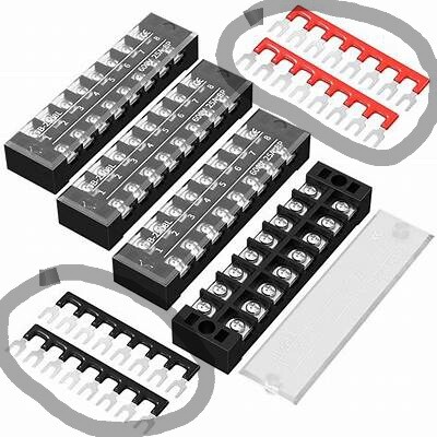
If you have the sort of thing pictured, you would use the ‘red’ and ‘black’ strips, one each side, and then connect the transformer wires to respective ‘bridged’ sides, as you indicated initially.
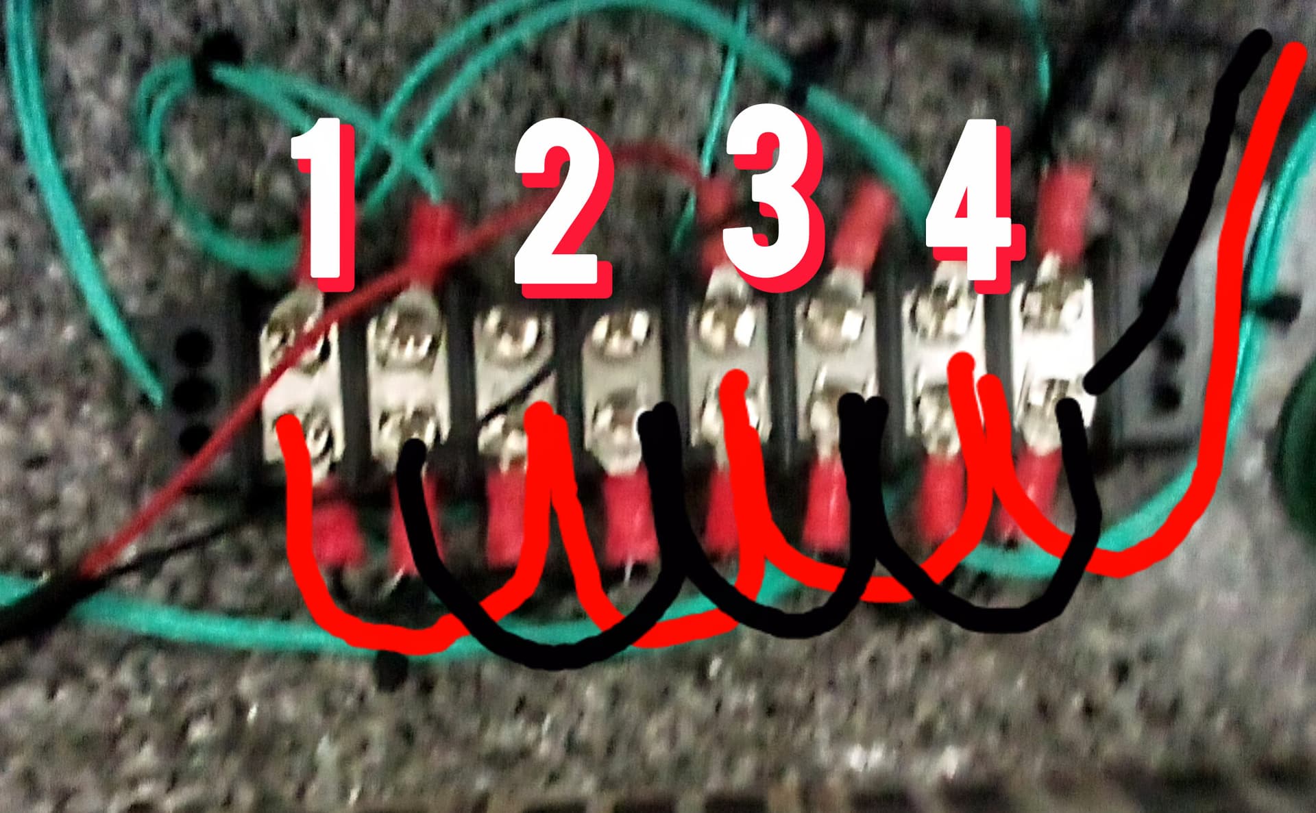
Each of the three Fastrak track ‘lock-ons’ would then be wired to a pair of screws exactly as if you were wiring it to the transformer alone. One cannot be backwards. You should check at this point, before attaching the Fastrak connections to actual track, with the power off and CW-80 unplugged, that you have continuity from the transformer screw through to each relevant contact point on the lock-ons.
Then attach the Fastrak connectors to the track and check connectivity again: one wire should ONLY go to the center rail and the other ONLY to the two outside rails. If not, you probably have a short in the track and will have to troubleshoot that.
Wow, I do not have those strips. I guess that’s the problem. Thank you so much.
Keep in mind that if you have the type of terminal strip that connects the two screw heads in each ‘row’ internally, you will create an immediate and very effective short if you use both the red and black ‘bus’ strip at the same time! You can check what type of terminal strip you have with the multimeter set on ohms/continuity.
Those three FasTrack Terminal Sections use wires with spade connectors that slip under the screws in the terminal block. If you don’t have those red terminal strips mentioned previously, just strip the insulation off a couple of pieces of your 18 gauge wire and place the bare wire across (under) the screws on each side of the terminal block.
1 Like
I wire with wire and crimp spade connectors to create “hubs” to connect my electricals by connecting one block to the next etc. to distribute power as needed since my layouts change a lot.
This is an example of the way I do things. This 8 position terminal strip is wired to create 4 pairs.
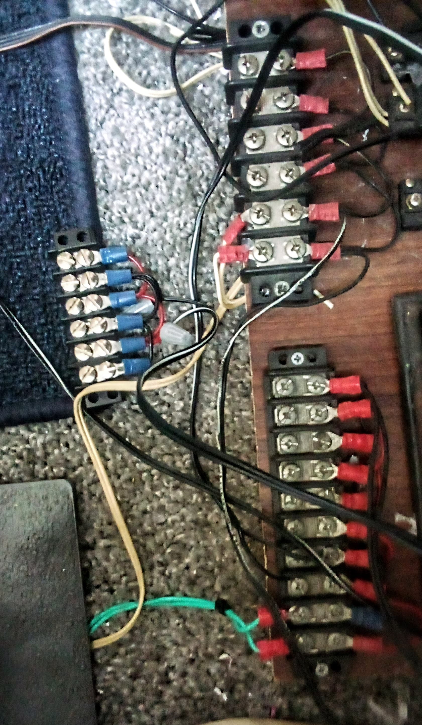
These two are the main power blocks for the layout. One, the 20 screw version, is 14 volt for lighting and the other is 20 volts for operating accessories. There’s also a small 3 pair block in the photo.
You may notice that I’ve salvaged A LOT of wire from old AC adapters ![]()
1 Like
Kudo’s for innovative wiring, instead of using one’s pocketbook to BUY ready made stuff. Where is the fun if not using creativity. Obviously I’m a cheapskake (tightwad). endmrw0410261437
Po folks make do ![]()